Toyota Tacoma (2015-2018) Service Manual: Components
COMPONENTS
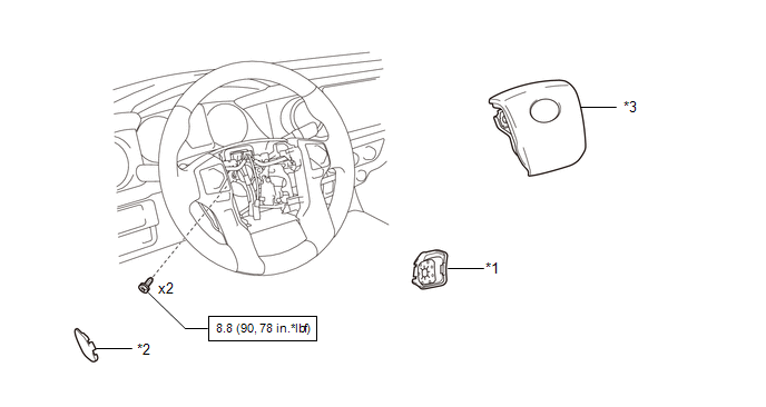
ILLUSTRATION
|
*1 |
LOWER NO. 2 STEERING WHEEL COVER |
*2 |
LOWER NO. 3 STEERING WHEEL COVER |
|
*3 |
STEERING PAD |
- |
- |
.png) |
N*m (kgf*cm, ft.*lbf): Specified torque |
- |
- |
 Steering Pad
...
 On-vehicle Inspection
ON-VEHICLE INSPECTION
PROCEDURE
1. INSPECT STEERING PAD (for Vehicle not Involved in Collision)
(a) Perform a diagnostic system check (See page
).
(b) With the steering pad installed on the vehi ...
Other materials:
Garage door opener
The garage door opener can be trained to operate garage doors, gates, entry
doors, door locks, home lighting systems, security systems, and other devices.
The garage door opener (HomeLink® Universal Transceiver) is manufactured under
license from HomeLink®.
Training the HomeLink® (for U.S. ...
Removal
REMOVAL
CAUTION / NOTICE / HINT
CAUTION:
Some of these service operations affect the SRS airbag system. Read
the precautionary notices concerning the SRS airbag system before servicing
(See page ).
If the side airbag was deployed, replace the front seat assembly with
a ne ...
Disassembly
DISASSEMBLY
PROCEDURE
1. INSPECT COUNTERSHAFT REVERSE GEAR THRUST CLEARANCE
(a) Using a dial indicator, measure the countershaft reverse gear thrust
clearance.
Standard clearance:
0.150 to 0.300 mm (0.0060 to 0.0118 in.)
If the clearance is outside the specification, repl ...
