Toyota Tacoma (2015-2018) Service Manual: Open in ABS Solenoid Relay Circuit (C146E,C146F)
DESCRIPTION
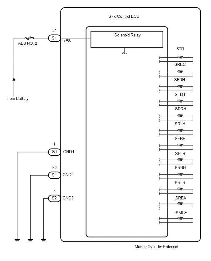
The ABS solenoid relay is built into the master cylinder solenoid.
This relay supplies power to each ABS solenoid. After the ignition switch is turned ON, if the initial check is OK, the relay turns on.
|
DTC No. |
DTC Detecting Conditions |
Trouble Areas |
|---|---|---|
|
C146E |
When either of following condition detected:
|
|
|
C146F |
The following condition continues for at least 0.2 seconds.
|
|
WIRING DIAGRAM
CAUTION / NOTICE / HINT
NOTICE:
- When replacing the skid control ECU (master cylinder solenoid), perform
zero point calibration (See page
.gif) ).
). - Inspect the fuses for circuits related to this system before performing the following inspection procedure.
PROCEDURE
|
1. |
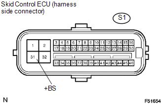
INSPECT SKID CONTROL ECU CONNECTOR (+BS TERMINAL VOLTAGE) |
|
(a) Disconnect the skid control ECU connector. |
|
(b) Measure the voltage.
Standard Voltage:
|
Tester Connection |
Specified Condition |
|---|---|
|
S1-31 (+BS) - Body ground |
10 to 14 V |
(c) Reconnect the skid control ECU connector.
| NG | .gif) |
REPAIR OR REPLACE HARNESS OR CONNECTOR |
|
.gif)
|
2. |
CHECK HARNESS OR CONNECTOR (GND - BODY GROUND) |
|
(a) Disconnect the skid control ECU connectors. |
|
.png)
(b) Measure the resistance.
Standard Resistance:
|
Tester Connection |
Specified Condition |
|---|---|
|
S1-1, 32 (GND1, GND2) - Body ground |
Below 1 Ω |
|
S2-4 (GND3) - Body ground |
Below 1 Ω |
(c) Reconnect the skid control ECU connectors.
| NG | |
REPAIR OR REPLACE HARNESS OR CONNECTOR (GND CIRCUIT) |
|
|
3. |
RECONFIRM DTC |
(a) Clear the DTCs (See page
).
(b) Check if the same DTCs are recorded.
|
Result |
Proceed to |
|---|---|
|
DTC output |
A |
|
DTC not output |
B |
| A | |
REPLACE MASTER CYLINDER SOLENOID |
| B | |
END |
 Abnormal Change in Output Signal of Rear Speed Sensor RH (Test Mode DTC) (C1277,...,C1416)
DESCRIPTION
Refer to DTCs C1401 and C1402 (See page ).
DTC Code
DTC Detection Condition
Trouble Area
C1277
C1278
Stored only during t ...
 ECM Communication Circuit Malfunction (C1203)
DESCRIPTION
The circuit sends TRAC, A-TRAC and VSC control information from the skid control
ECU (master cylinder solenoid) to the ECM, and engine control information from the
ECM to the skid con ...
Other materials:
Diagnostic Trouble Code Chart
DIAGNOSTIC TROUBLE CODE CHART
Air Conditioning System
DTC Code
Detection Item
Memory
See page
B1412
Ambient Temperature Sensor Circuit
Memorized
(4 seconds or more)
B1413
...
Diagnosis System
DIAGNOSIS SYSTEM
1. CHECK DLC3
(a) Check the DLC3 (See page ).
2. INSPECT BATTERY VOLTAGE
(a) Measure the battery voltage.
Standard Voltage:
11 to 14 V
If the voltage is below 11 V, recharge or replace the battery.
3. SELF-DIAGNOSTIC MODE (OPERATING IGNITION KEY CYLINDER)
(a) Switch to se ...
Front Radar Sensor Region Code Mismatch (C1A0A)
DESCRIPTION
When the destination information in the millimeter wave radar sensor assembly
and forward recognition camera do not match, DTC C1A0A is stored.
DTC No.
Detection Item
DTC Detection Condition
Trouble Area
MIL
C1A0 ...
