Toyota Tacoma (2015-2018) Service Manual: System Diagram
SYSTEM DIAGRAM
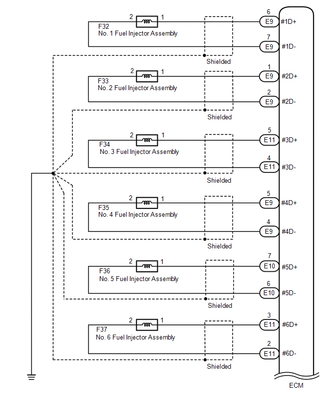
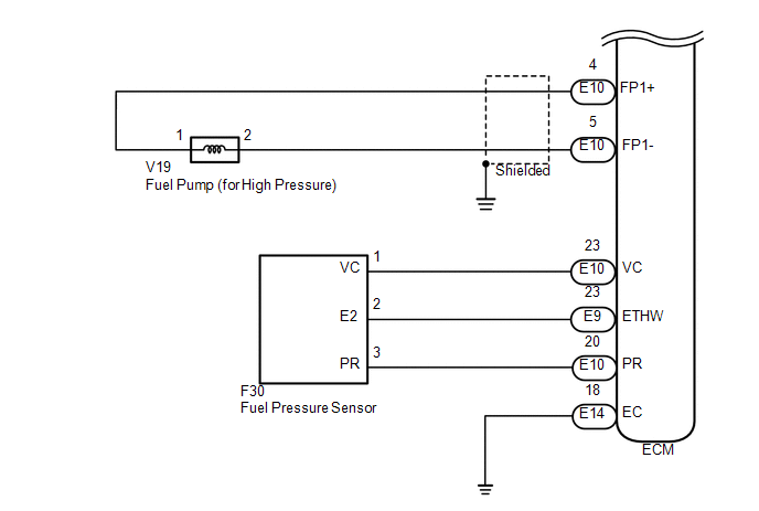
1. HIGH PRESSURE SIDE FUEL SYSTEM WIRING DIAGRAM
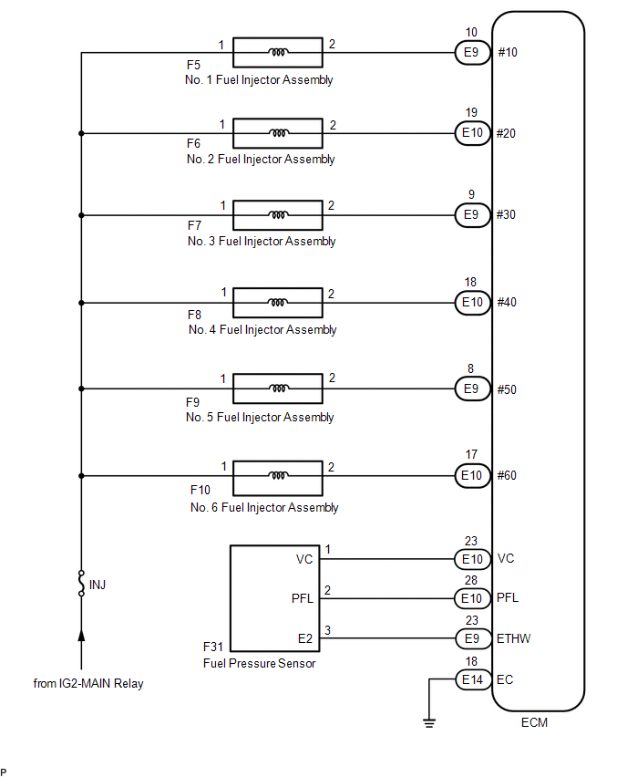
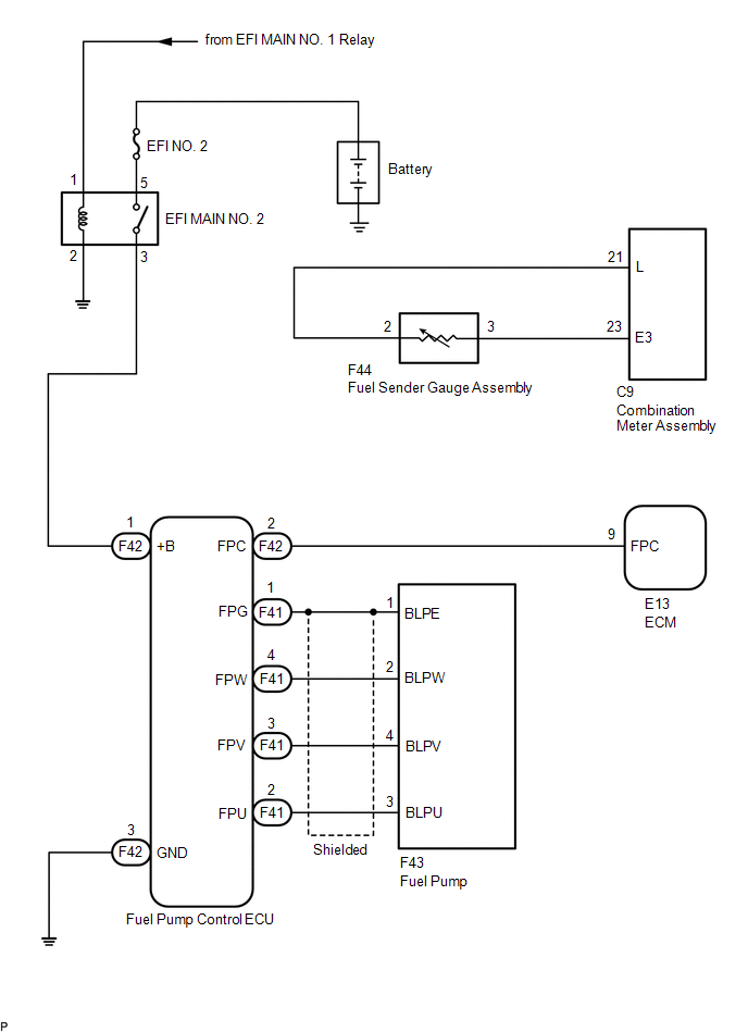
2. LOW PRESSURE SIDE FUEL SYSTEM WIRING DIAGRAM
 Parts Location
PARTS LOCATION
ILLUSTRATION
ILLUSTRATION
ILLUSTRATION
...
 On-vehicle Inspection
ON-VEHICLE INSPECTION
PROCEDURE
1. CHECK FUEL PUMP OPERATION AND INSPECT FOR FUEL LEAK
(a) Connect the Techstream to the DLC3.
(1) Turn the ignition switch to ON.
NOTICE:
Do not start the engine ...
Other materials:
How To Proceed With Troubleshooting
CAUTION / NOTICE / HINT
HINT:
Use these procedures to troubleshoot the key reminder warning system.
*: Use the Techstream.
PROCEDURE
1.
VEHICLE BROUGHT TO WORKSHOP
NEXT
...
Tire Pressure Warning Light Circuit
DESCRIPTION
If the tire pressure warning ECU and receiver detects any problems, the tire
pressure warning light blinks for 1 minute then illuminates, and tire pressure monitoring
is disabled at the same time. At this time, the ECU stores a DTC in memory.
Connecting terminals TC and CG of the D ...
Components
COMPONENTS
ILLUSTRATION
*A
w/ Off Road Package
-
-
*1
NO. 1 ENGINE UNDER COVER SUB-ASSEMBLY
*2
NO. 2 ENGINE UNDER COVER SUB-ASSEMBLY
*3
FRONT UPPER FENDER APRON SEAL
...
