Toyota Tacoma (2015-2018) Service Manual: Inspection
INSPECTION
PROCEDURE
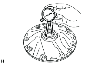
1. INSPECT FRONT OIL PUMP BODY SUB-ASSEMBLY
|
(a) Using a dial indicator, measure the inside diameter of the front oil pump body sub-assembly bushing. Maximum inside diameter: 38.138 mm (1.50 in.) If the inside diameter is more than the maximum inside diameter, replace the front oil pump body sub-assembly. |
|
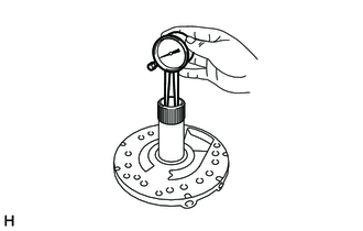
2. INSPECT STATOR SHAFT ASSEMBLY
|
(a) Using a dial indicator, measure the inside diameter of the stator shaft assembly bushing. Maximum inside diameter: 22.227 mm (0.875 in.) If the inside diameter is more than the maximum inside diameter, replace the stator shaft assembly. |
|
3. INSPECT CLEARANCE OF OIL PUMP ASSEMBLY
|
(a) Push the front oil pump driven gear to one side of the front oil pump body sub-assembly. |
|
(b) Using a feeler gauge, measure the clearance.
Standard body clearance:
0.10 to 0.17 mm (0.00394 to 0.00669 in.)
If the body clearance is more than the standard clearance, check the front oil pump drive gear, front oil pump driven gear and front oil pump body sub-assembly.
|
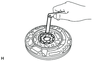
(c) Using a feeler gauge, measure the clearance between the front oil pump driven gear teeth and the front oil pump drive gear teeth. Standard tip clearance: 0.07 to 0.15 mm (0.00276 to 0.00590 in.) If the tip clearance is more than the standard clearance, check the front oil pump drive gear, front oil pump driven gear and front oil pump body sub-assembly. |
|
|
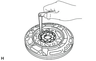
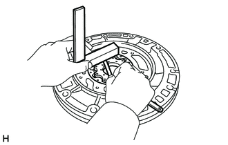
(d) Using a steel straightedge and a feeler gauge, measure the side clearance of both gears. Standard side clearance: 0.03 to 0.05 mm (0.00118 to 0.00196 in.) If the side clearance is more than the standard thickness, check the front oil pump drive gear, front oil pump driven gear and front oil pump body sub-assembly. |
|
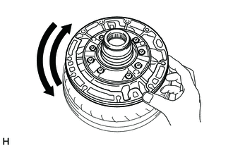
4. INSPECT OIL PUMP DRIVE GEAR ROTATION
(a) Install the oil pump assembly to the torque converter assembly.
|
(b) Check that the front oil pump drive gear rotates smoothly. |
|
(c) Remove the oil pump assembly from the torque converter assembly.
 Disassembly
DISASSEMBLY
PROCEDURE
1. REMOVE FRONT OIL PUMP BODY O-RING
(a) Remove the front oil pump body O-ring from the oil pump assembly.
2. SECURE OIL ...
 Reassembly
REASSEMBLY
PROCEDURE
1. INSTALL FRONT OIL PUMP OIL SEAL
(a) Using SST and a hammer, install a new front oil pump oil seal to
the front oil pump body sub-assembly.
SST: 09350-30020 ...
Other materials:
Lock Switch Circuit
WIRING DIAGRAM
PROCEDURE
1.
CHECK REAR DIFFERENTIAL LOCK INDICATOR LIGHT
(a) Turn the ignition switch to ON.
(b) for 4WD:
Finish switching to L4.
(c) Check the rear differential lock indicator light.
(d) Press the differential lock switch.
(e) After 60 secon ...
Rear Cross Traffic Alert Buzzer
Components
COMPONENTS
ILLUSTRATION
Installation
INSTALLATION
PROCEDURE
1. INSTALL REAR CROSS TRAFFIC ALERT BUZZER
(a) Engage the clamp to install the rear cross traffic alert buzzer.
(b) Connect the connector.
2. INSTALL QUARTER INSIDE TRIM BOARD LH (for Double Cab)
(See page )
3. ...
Installation
INSTALLATION
PROCEDURE
1. INSTALL POWER STEERING LINK
(a) Insert the power steering link into the vehicle in the order shown in the
illustration.
Install in this Direction (1)
Install in this Direction (2)
(b) Temporarily install the po ...
