Toyota Tacoma (2015-2018) Service Manual: On-vehicle Inspection
ON-VEHICLE INSPECTION
PROCEDURE
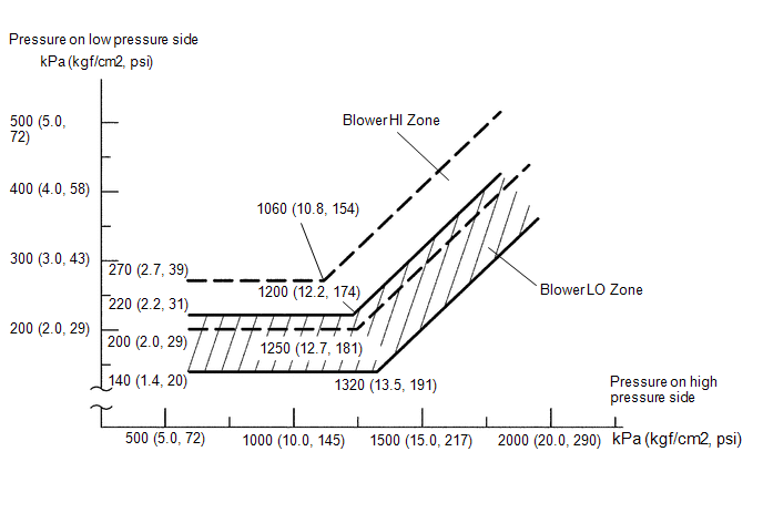
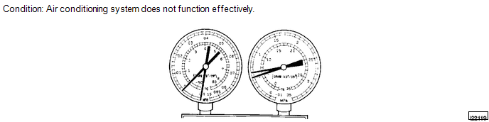
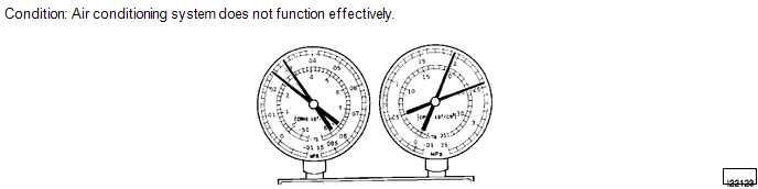
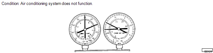
1. INSPECT REFRIGERANT PRESSURE WITH MANIFOLD GAUGE SET
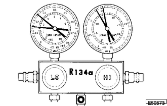
(a) This is a method to specify trouble areas by using a manifold gauge set. Read the manifold gauge pressure when the following conditions are established.
Test conditions:
- Engine has been warmed up.
- All doors are fully open.
- A/C switch is ON.
- Engine is running at 1,500 rpm.
- Air inlet mode selector damper is set at recirculation.
- Temperature control switch is in MAX. COLD position.
- Blower speed control switch is in HI position.
- Air temperature at the air inlet is 30 to 35°C (86 to 95°F).
Gauge readings (Reference)
|
(1) When the refrigerant volume is proper: Gauge reading: Low pressure side: 150 to 250 kPa (1.5 to 2.5 kgf/cm2, 22 to 36 psi) High pressure side: 1370 to 1570 kPa (14.0 to 16.0 kgf/cm2, 199 to 228 psi) |
|
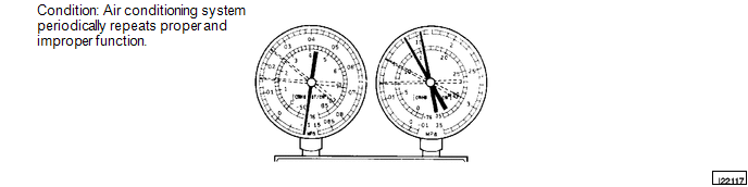
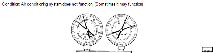
(2) When there is moisture in the refrigeration system:
|
Symptoms |
Probable Cause |
Diagnosis |
Corrective Actions |
|---|---|---|---|
|
During operation, pressure on low pressure side cycles between normal and vacuum |
Moisture in refrigeration system freezes at expansion valve orifice, causing temporary stop of cycle. However, when melted, normal state restored |
|
|
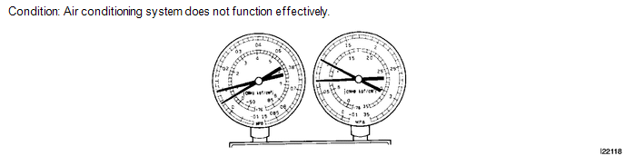
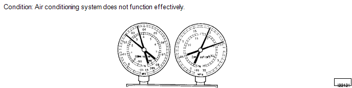
(3) When cooling is insufficient:
|
Symptoms |
Probable Cause |
Diagnosis |
Corrective Actions |
|---|---|---|---|
|
Gas leakage from refrigeration system |
|
|
(4) When the circulation of the refrigerant is poor:
|
Symptoms |
Probable Cause |
Diagnosis |
Corrective Action |
|---|---|---|---|
|
Refrigerant flow obstructed by dirt in condenser |
Condenser clogged |
Replace condenser |
(5) When the refrigerant does not circulate:
|
Symptoms |
Probable Causes |
Diagnosis |
Corrective Actions |
|---|---|---|---|
|
|
Refrigerant does not circulate |
|
(6) When the refrigerant is overcharged or cooling of condenser is insufficient:
|
Symptoms |
Probable Causes |
Diagnosis |
Corrective Actions |
|---|---|---|---|
|
Pressure extremely high on both low and high pressure sides |
|
|
|
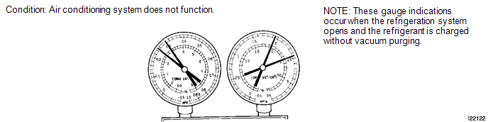
(7) When there is air in the refrigeration system:
|
Symptoms |
Probable Cause |
Diagnosis |
Corrective Actions |
|---|---|---|---|
|
Air in refrigeration system |
|
|
(8) When the expansion valve malfunctions:
|
Symptoms |
Probable Cause |
Diagnosis |
Corrective Action |
|---|---|---|---|
|
Trouble in expansion valve |
|
Replace expansion valve |
(9) When the compressor is defective:
|
Symptoms |
Probable Cause |
Diagnosis |
Corrective Action |
|---|---|---|---|
|
Internal leakage in compressor |
|
Repair or replace compressor |

 Replacement
REPLACEMENT
PROCEDURE
1. RECOVER REFRIGERANT FROM REFRIGERATION SYSTEM
(a) Start up the engine.
(b) Turn the A/C switch to ON.
(c) Operate the cooler compressor with an engine speed of approximat ...
Other materials:
Removal
REMOVAL
PROCEDURE
1. REMOVE REFRIGERANT FROM REFRIGERATION SYSTEM
2. REMOVE AIR CONDITIONER PRESSURE SENSOR
(a) Disconnect the connector.
(b) Using a 27 mm deep socket wrench, remove the air conditioner pressure
sensor.
T ...
System Diagram
SYSTEM DIAGRAM
Transmitting ECU (Transmitter)
Receiving ECU
Signal
Communication Method
4 wheel drive control ECU
Skid control ECU (Brake actuator assembly)
High-Low actuator fail
4WD status ...
Lost Communication with Cruise Control Front Distance Range Sensor (U0235)
DESCRIPTION
The millimeter wave radar sensor assembly is connected to the skid control ECU
(master cylinder solenoid)*1 or skid control ECU (brake actuator assembly)*2 via
CAN communication. If communication with the skid control ECU (master cylinder solenoid)*1
or skid control ECU (brake act ...
