Toyota Tacoma (2015-2018) Service Manual: Accelerator Pedal
Components
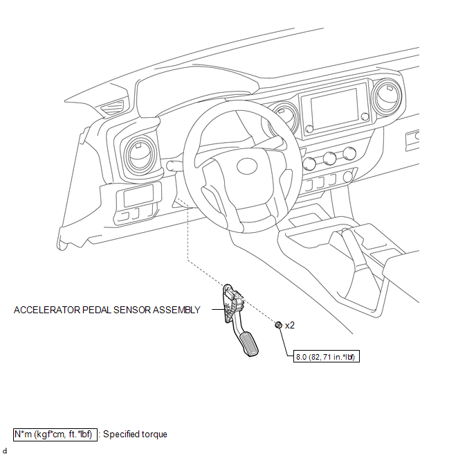
COMPONENTS
ILLUSTRATION
On-vehicle Inspection
ON-VEHICLE INSPECTION
PROCEDURE
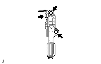
1. INSPECT ACCELERATOR PEDAL SENSOR ASSEMBLY
(a) Connect the Techstream to the DLC3.
(b) Turn the ignition switch to ON.
(c) Turn the Techstream on.
(d) Enter the following menus: Powertrain / Engine / Data List / Accelerator Position Sensor No. 1 Voltage and Accelerator Position Sensor No. 2 Voltage.
(e) When depressing or releasing the accelerator pedal, check that the values of Accelerator Position Sensor No. 1 Voltage and Accelerator Position Sensor No. 2 Voltage are within the specification.
Standard Voltage:
|
Item |
Condition |
Specified Condition |
|---|---|---|
|
Accelerator Position Sensor No. 1 Voltage |
Released |
0.5 to 1.1 V |
|
Depressed |
2.6 to 4.5 V |
|
|
Accelerator Position Sensor No. 2 Voltage |
Released |
1.2 to 2.0 V |
|
Depressed |
3.4 to 4.75 V |
If the result is not as specified, check the accelerator pedal sensor assembly, wire harness and ECM.
Installation
INSTALLATION
PROCEDURE
1. INSTALL ACCELERATOR PEDAL SENSOR ASSEMBLY
NOTICE:
This accelerator pedal sensor assembly does not require lubrication. Do not apply oil or other lubrication to the accelerator pedal sensor assembly. If applied, the accelerator pedal sensor assembly must be replaced.
(a) Install the accelerator pedal sensor assembly to the vehicle body with the 2 bolts.
Torque:
8.0 N·m {82 kgf·cm, 71 in·lbf}
NOTICE:
- Avoid any physical impact to the accelerator pedal sensor assembly.
- Do not disassemble the accelerator pedal sensor assembly.
(b) Connect the connector to the accelerator pedal sensor assembly.
Removal
REMOVAL
PROCEDURE
1. REMOVE ACCELERATOR PEDAL SENSOR ASSEMBLY
NOTICE:
This accelerator pedal sensor assembly does not require lubrication. Do not apply oil or other lubrication to the accelerator pedal sensor assembly. If applied, the accelerator pedal sensor assembly must be replaced.
|
(a) Disconnect the connector from the accelerator pedal sensor assembly. |
|
(b) Remove the 2 bolts and accelerator pedal sensor assembly from the vehicle body.

 Air Fuel Ratio Sensor
Components
COMPONENTS
ILLUSTRATION
Removal
REMOVAL
PROCEDURE
1. REMOVE AIR FUEL RATIO SENSOR (for Bank 1 Sensor 1)
(a) Disconnect the air fuel ratio sensor connector.
...
Other materials:
High Pitched Horn
Components
COMPONENTS
ILLUSTRATION
Removal
REMOVAL
PROCEDURE
1. REMOVE RADIATOR GRILLE
Click here
2. REMOVE HIGH PITCHED HORN ASSEMBLY
(a) Disconnect the connector.
(b) Remove the bolt and high pitched horn assembly.
Inspection
...
Customize Parameters
CUSTOMIZE PARAMETERS
PROCEDURE
1. CUSTOMIZE POWER WINDOW CONTROL SYSTEM
HINT:
The following items can be customized.
NOTICE:
When the customer requests a change in a function, first make sure that
the function can be customized.
Record the current settings before customizing.
...
Installation
INSTALLATION
PROCEDURE
1. INSTALL REAR SEAT 3 POINT TYPE OUTER BELT ASSEMBLY
(a) Before installing the rear seat 3 point type outer belt assembly,
check the ELR function.
Text in Illustration
*a
Unlock
*b
...
