Toyota Tacoma (2015-2018) Service Manual: Oil Pressure Switch
Components
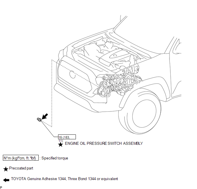
COMPONENTS
ILLUSTRATION
Removal
REMOVAL
PROCEDURE
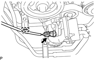
1. REMOVE ENGINE OIL PRESSURE SWITCH ASSEMBLY
|
(a) Disengage the clamp and disconnect the engine oil pressure switch connector. |
|
|
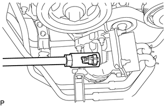
(b) Using a 24 mm deep socket wrench, remove the engine oil pressure switch assembly. |
|
Inspection
INSPECTION
PROCEDURE
1. INSPECT ENGINE OIL PRESSURE SWITCH ASSEMBLY
(a) Disconnect the engine oil pressure switch connector.
(b) Start the engine.
(c) Measure the resistance according to the value(s) in the table below.
Standard Resistance:
|
Tester Connection |
Condition |
Specified Condition |
|---|---|---|
|
1 - Body ground |
Engine stopped |
Below 1 Ω |
|
Engine idling |
10 kΩ or higher |
If the result is not as specified, replace the engine oil pressure switch assembly.
(d) Connect the engine oil pressure switch connector.
Installation
INSTALLATION
PROCEDURE
1. INSTALL ENGINE OIL PRESSURE SWITCH ASSEMBLY
(a) Apply adhesive to 2 or 3 threads of the engine oil pressure switch assembly.
Adhesive:
Toyota Genuine Adhesive 1344, Three Bond 1344 or equivalent
NOTICE:
Do not apply adhesive to the oil inlet port of the engine oil pressure switch assembly.
(b) Using a 24 mm deep socket wrench, install the engine oil pressure switch assembly.
Torque:
15 N·m {153 kgf·cm, 11 ft·lbf}
NOTICE:
Do not start the engine within 1 hour of installation.
(c) Connect the engine oil pressure switch connector and attach the clamp.
2. INSPECT FOR ENGINE OIL LEAK
.gif)
3. INSPECT ENGINE OIL LEVEL
 Oil Level Sensor
Components
COMPONENTS
ILLUSTRATION
ILLUSTRATION
Inspection
INSPECTION
PROCEDURE
1. INSPECT ENGINE OIL LEVEL SENSOR
(a) Measure the resistance according to the value(s) in th ...
 Oil Pump
...
Other materials:
Brake Fluid(for Hydraulic Brake Booster)
On-vehicle Inspection
ON-VEHICLE INSPECTION
PROCEDURE
1. INSPECT FLUID LEVEL IN RESERVOIR
(a) Turn the ignition switch to OFF, and depress the brake pedal more
than 40 times (until the pedal reaction feels light and pedal stroke becomes
longer), and adjust the fluid level to ...
Installation
INSTALLATION
PROCEDURE
1. INSTALL NO. 1 FUEL TANK PROTECTOR
(a) Install the No. 1 fuel tank protector to the fuel tank assembly with the
4 clips.
2. INSTALL FUEL SUCTION TUBE SET GASKET
Click here
3. INSTALL FUEL SUCTION TUBE WITH PUMP AND GAUGE ASSEMBLY
Click here
4. INSTALL FUEL PUMP ...
Removal
REMOVAL
CAUTION / NOTICE / HINT
HINT:
If the bumper is damaged, there is a possibility that the installation area of
the blind spot monitor sensor may be deformed and the blind spot monitor system
may not operate correctly, so visually inspect the blind spot monitor sensor installation
area ...
