Toyota Tacoma (2015-2018) Service Manual: Oil Level Sensor
Components
COMPONENTS
ILLUSTRATION
ILLUSTRATION
Inspection
INSPECTION
PROCEDURE
1. INSPECT ENGINE OIL LEVEL SENSOR
|
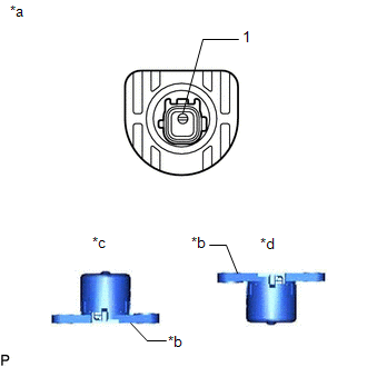
(a) Measure the resistance according to the value(s) in the table below. Standard Resistance:
If the result is not as specified, replace the engine oil level sensor. |
|
Installation
INSTALLATION
PROCEDURE
1. INSTALL ENGINE OIL LEVEL SENSOR
(a) Apply a light coat of engine oil to the O-ring of the engine oil level sensor.
|
(b) Install a new clip to the engine oil level sensor as shown in the illustration. |
|

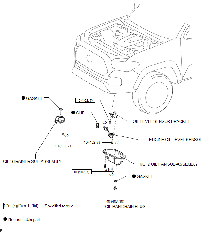
(c) Install the oil level sensor bracket with the 2 nuts.
Torque:
10 N·m {102 kgf·cm, 7 ft·lbf}
(d) Install the engine oil level sensor with the 2 nuts.
Torque:
10 N·m {102 kgf·cm, 7 ft·lbf}
(e) Engage the clamp and disconnect the engine oil level sensor connector.
2. INSTALL OIL STRAINER SUB-ASSEMBLY
.gif)
3. INSTALL NO. 2 OIL PAN SUB-ASSEMBLY
4. ADD ENGINE OIL
5. INSPECT FOR OIL LEAK
6. INSPECT ENGINE OIL LEVEL
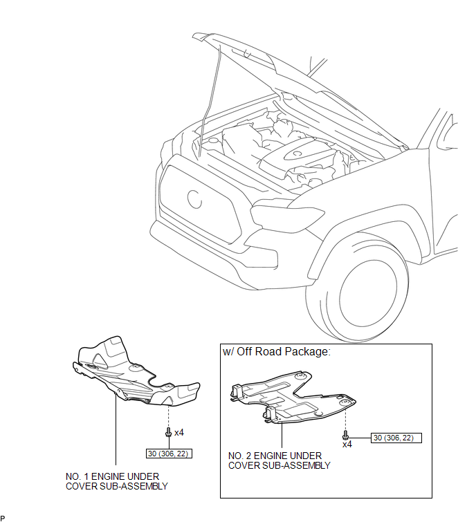
7. INSTALL NO. 1 ENGINE UNDER COVER SUB-ASSEMBLY
8. INSTALL NO. 2 ENGINE UNDER COVER SUB-ASSEMBLY (w/ Off Road Package)
Removal
REMOVAL
PROCEDURE
1. REMOVE NO. 2 ENGINE UNDER COVER SUB-ASSEMBLY (w/ Off Road Package)
2. REMOVE NO. 1 ENGINE UNDER COVER SUB-ASSEMBLY
3. DRAIN ENGINE OIL
.gif)
4. REMOVE NO. 2 OIL PAN SUB-ASSEMBLY
5. REMOVE OIL STRAINER SUB-ASSEMBLY
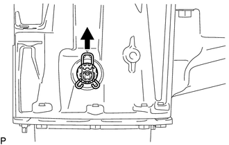
6. REMOVE ENGINE OIL LEVEL SENSOR
|
(a) Disengage the clamp and disconnect the engine oil level sensor connector. |
|
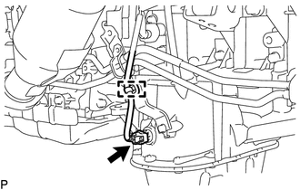
|
(b) Remove the clip from the engine oil level sensor. |
|
|
(c) Remove the 2 nuts from the engine oil level sensor. |
|
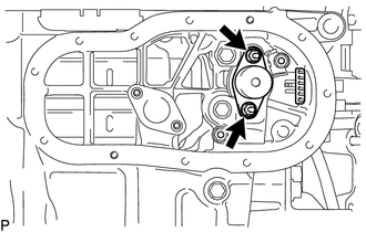
|
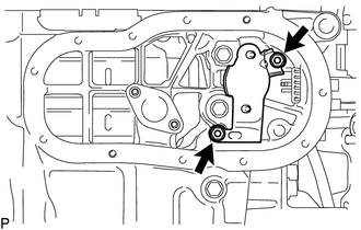
(d) Remove the 2 nuts and oil level sensor bracket. |
|
(e) Remove the engine oil level sensor.
 Replacement
REPLACEMENT
CAUTION / NOTICE / HINT
CAUTION:
Prolonged and repeated contact with engine oil will result in the removal
of natural oils from the skin, leading to dryness, irritation and ...
 Oil Pressure Switch
Components
COMPONENTS
ILLUSTRATION
Removal
REMOVAL
PROCEDURE
1. REMOVE ENGINE OIL PRESSURE SWITCH ASSEMBLY
(a) Disengage the clamp and disconnect the engine oil pressure switch ...
Other materials:
Removal
REMOVAL
PROCEDURE
1. PRECAUTION
NOTICE:
After turning the ignition switch off, waiting time may be required before disconnecting
the cable from the negative (-) battery terminal. Therefore, make sure to read the
disconnecting the cable from the negative (-) battery terminal notices before pr ...
Invalid Data Received from Deceleration Sensor (C1442,C1443)
DESCRIPTION
The skid control ECU (master cylinder solenoid) receives signals from the yaw
rate and acceleration sensor (airbag sensor assembly) via the CAN communication
system.
The airbag sensor assembly has a built-in yaw rate and acceleration sensor.
DTC Code
DTC Dete ...
Road Test
ROAD TEST
1. PROBLEM SYMPTOM CONFIRMATION
(a) Based on the result of the customer problem analysis, try to reproduce the
symptoms. If the problem is that the transmission does not shift up or down, or
that the shift point is too high or too low, conduct the following road test referring
to t ...
