Toyota Tacoma (2015-2018) Service Manual: Removal
REMOVAL
PROCEDURE
1. REMOVE FRONT WHEEL
2. INSPECT FRONT SUSPENSION LOWER ARM
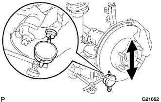
(a) Install the hub nuts onto the disc.
(b) Using a dial indicator, check the lower ball joint for excessive play when you push the hub nuts up and down with a force of 294 N (30 kgf, 66 lbf).
Maximum:
0.5 mm (0.020 in.)
HINT:
If it is not within the specification, replace the lower arm.
3. SEPARATE FRONT SHOCK ABSORBER WITH COIL SPRING
(a) Remove the bolt, nut and washer.
(b) Separate the front shock absorber with coil spring from the suspension lower arm.
4. REMOVE FRONT SUSPENSION LOWER ARM
.png)
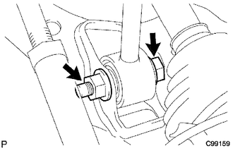
(a) Remove the 2 bolts, and separate the front lower ball joint attachment from the front axle.
|
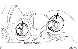
(b) Place matchmarks on the camber adjust cam No. 2 and toe adjust cam. |
|
(c) Remove the nut, camber adjust cam No. 2, camber adjust cam No. 1, bolt, toe adjust cam, toe adjust plate No. 2 and front suspension lower arm.
|
(d) Remove the cotter pin and the nut. |
|
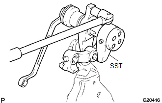
(e) Using SST, remove the front lower ball joint attachment LH.
SST: 09628-00011
 Disassembly
DISASSEMBLY
PROCEDURE
1. REMOVE FRONT LOWER ARM BUSH NO. 1
(a) Using a hammer and chisel, raise the flange of the bush diagonally as shown
in the illustration.
(b) Using SST, remove ...
 Inspection
INSPECTION
PROCEDURE
1. INSPECT FRONT SUSPENSION LOWER ARM
(a) Flip the ball joint stud back and forth 5 times, as shown in the illustration,
before installing the nut.
(b) Using a torque wren ...
Other materials:
System Description
SYSTEM DESCRIPTION
1. ILLUMINATED ENTRY SYSTEM
(a) The illuminated entry system has the following control functions:
Control
Outline
Lights that Operate
Actuation Area-linked*1
When a registered key enters any actuation area around the ...
Diagnostic Trouble Code Chart
DIAGNOSTIC TROUBLE CODE CHART
Audio and Visual System
DTC Code
Detection Item
See page
B1324
Lost Communication with Meter
B1532
LVDS Signal Malfunction (from Extension Module)
...
Noise Occurs from V-ribbed Belt or Generator Assembly
PROCEDURE
1.
CONFIRM PROBLEM SYMPTOM
(a) Confirm the problem symptom.
Result
Result
Proceed to
Noise occurs from fan and generator V belt
A
Noise occurs from generator assembly
B
...
