Toyota Tacoma (2015-2018) Service Manual: Microphone Amplifier
Components
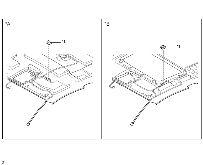
COMPONENTS
ILLUSTRATION
|
*A |
w/o Sliding Roof |
*B |
w/ Sliding Roof |
|
*1 |
TELEPHONE MICROPHONE ASSEMBLY |
- |
- |
Removal
REMOVAL
PROCEDURE
1. REMOVE ROOF HEADLINING ASSEMBLY (for Double Cab)
Click here .gif)
2. REMOVE ROOF HEADLINING ASSEMBLY (for Access Cab)
Click here
3. REMOVE TELEPHONE MICROPHONE ASSEMBLY
|
(a) Disconnect the connector. |
|
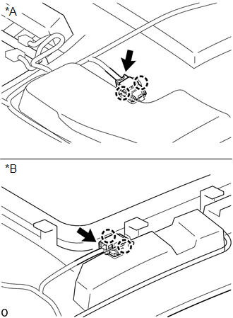
(b) Disengage the 2 claws to remove the telephone microphone assembly.
Installation
INSTALLATION
PROCEDURE
1. INSTALL TELEPHONE MICROPHONE ASSEMBLY
(a) Engage the 2 claws to install the telephone microphone assembly.
(b) Connect the connector.
2. INSTALL ROOF HEADLINING ASSEMBLY (for Double Cab)
Click here .gif)
3. INSTALL ROOF HEADLINING ASSEMBLY (for Access Cab)
Click here
 Installation
INSTALLATION
PROCEDURE
1. INSTALL FRONT NO. 2 SPEAKER ASSEMBLY RH
(a) Connect the connector.
(b) Install the front No. 2 speaker assembly RH with the 2 bolts.
Torque:
8.4 N·m {86 kgf·cm, 74 i ...
 Noise Filter(for 2gr-fks)
Components
COMPONENTS
ILLUSTRATION
Removal
REMOVAL
PROCEDURE
1. DISCONNECT CABLE FROM NEGATIVE BATTERY TERMINAL
2. REMOVE V-BANK COVER
(See page )
3. REMOVE AIR CLEANER ASSEMBLY
(See ...
Other materials:
Precaution
PRECAUTION
IGNITION SWITCH EXPRESSIONS
(a) The type of ignition switch used on this model differs according to the specifications
of the vehicle. The expressions listed in the table below are used in this section.
Expression
Ignition Switch (Position)
Engine Swi ...
USB Audio System Recognition/Play Error
DESCRIPTION
When a USB device or "iPod" is connected to the USB jack of the No. 1 stereo
jack adapter assembly, it must have playable files. The device must also communicate
with and be recognized by the navigation receiver assembly. This diagnosis procedure
is for when a device is ...
Freeze Frame Data
FREEZE FRAME DATA
1. FREEZE FRAME DATA
(a) Whenever a meter DTC is detected, the combination meter assembly stores the
current vehicle state as freeze frame data.
2. CHECK FREEZE FRAME DATA
(a) Connect the Techstream to the DLC3.
(b) Turn the ignition switch to ON.
(c) Turn the Techstream on ...
