Toyota Tacoma (2015-2018) Service Manual: Removal
REMOVAL
CAUTION / NOTICE / HINT
.png) Text in Illustration
Text in Illustration
|
*a |
Object Exceeding Weight Limit of Transmission Jack |
- Be sure to perform this procedure with several people as the rear differential carrier assembly is very heavy.
- Be sure to follow the procedure described in the repair manual, or the transmission jack may suddenly drop or a part may fall.
PROCEDURE
1. REMOVE REAR WHEELS
2. REMOVE REAR PROPELLER SHAFT ASSEMBLY (for 2WD)
(See page .gif) )
)
3. REMOVE REAR PROPELLER SHAFT ASSEMBLY (for 4WD)
(See page )
4. DRAIN DIFFERENTIAL OIL
(See page )
5. REMOVE REAR AXLE SHAFT WITH BACKING PLATE LH
(See page )
6. REMOVE REAR AXLE SHAFT WITH BACKING PLATE RH
HINT:
Use the same procedure described for the LH side.
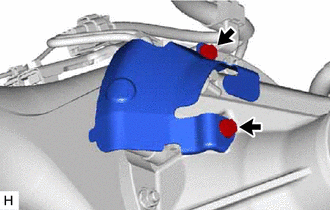
7. REMOVE REAR DIFFERENTIAL PROTECTOR
|
(a) Remove the 2 bolts and differential protector from the differential carrier assembly. |
|
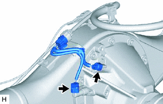
8. REMOVE REAR DIFFERENTIAL CARRIER ASSEMBLY
|
(a) Disconnect the 2 connectors. |
|
|
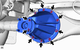
(b) Remove the 10 nuts, 10 washers and rear differential carrier assembly. NOTICE: Be careful not to damage the contact surface. CAUTION: The rear differential carrier assembly is a heavy component. Make sure that it is supported securely. NOTICE:
|
|
9. REMOVE REAR DIFFERENTIAL CARRIER GASKET
 Components
COMPONENTS
ILLUSTRATION
HINT:
The following specifications are for BD22AN (w/ Differential Lock). BD22AN differentials
are equipped with M10 rear differential carrier to rear axel housing fastene ...
 Installation
INSTALLATION
CAUTION / NOTICE / HINT
HINT:
The following procedures are for BD22 (w/ Differential Lock).
PROCEDURE
1. INSTALL REAR DIFFERENTIAL CARRIER ASSEMBLY
(a) Clean the contact surfaces of ...
Other materials:
Precaution
PRECAUTION
PRECAUTION FOR DISCONNECTING CABLE FROM NEGATIVE BATTERY TERMINAL
NOTICE:
When disconnecting the cable from the negative (-) battery terminal,
initialize the following systems after the cable is reconnected.
Click here
If the battery has been discharged and char ...
Door Unlock Detection Switch Circuit
DESCRIPTION
The main body ECU (multiplex network body ECU) detects the condition of each
door unlock detection switch.
WIRING DIAGRAM
CAUTION / NOTICE / HINT
NOTICE:
If the main body ECU (multiplex network body ECU) is replaced, refer to Registration
(See page ).*1
*1: w/ Smart K ...
How To Proceed With Troubleshooting
CAUTION / NOTICE / HINT
HINT:
Use the following procedures to troubleshoot the cruise control system.
*: Use the Techstream.
PROCEDURE
1.
VEHICLE BROUGHT TO WORKSHOP
NEXT
...
