Toyota Tacoma (2015-2018) Service Manual: Network Gateway Ecu
Components
COMPONENTS
ILLUSTRATION
Installation
INSTALLATION
PROCEDURE
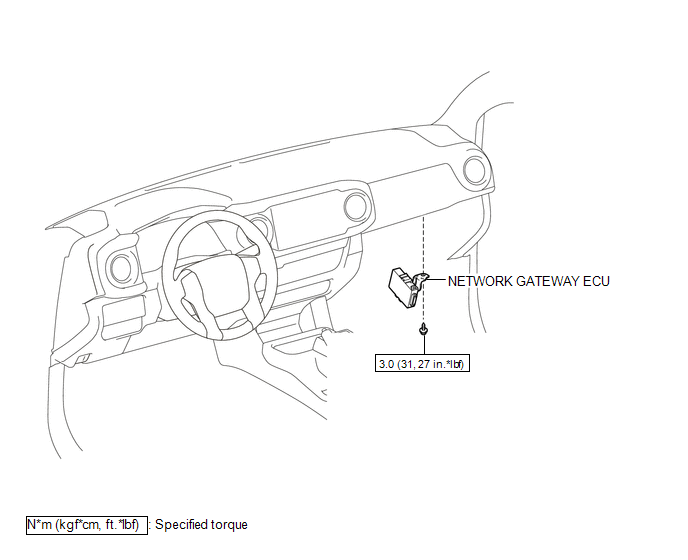
1. INSTALL NETWORK GATEWAY ECU
(a) Install the network gateway ECU with the bolt.
Torque:
3.0 N┬Ęm {31 kgf┬Ęcm, 27 in┬Ęlbf}
(b) Connect the connector.
2. INSTALL LOWER INSTRUMENT PANEL ASSEMBLY
(See page .gif) )
)
Removal
REMOVAL
PROCEDURE
1. REMOVE LOWER INSTRUMENT PANEL ASSEMBLY
(See page .gif) )
)
2. REMOVE NETWORK GATEWAY ECU
|
(a) Disconnect the connector. |
|
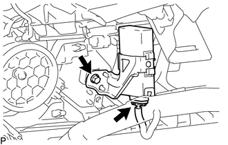
(b) Remove the bolt and network gateway ECU.
 Tire Pressure Monitor ECU Communication Stop Mode
DESCRIPTION
Detection Item
Symptom
Trouble Area
Tire Pressure Monitor ECU Communication Stop Mode
Either condition is met:
C ...

Other materials:
Air Mix Damper Position Sensor Circuit (Driver Side) (B1436/36)
DESCRIPTION
This sensor detects the position of the air mix damper (for driver side) and
sends the appropriate signals to the air conditioning amplifier assembly. The position
sensor is built into the No. 3 air conditioning radiator damper servo sub-assembly
(for driver side air mix).
...
Trailer towing
Your vehicle is designed primarily as a passenger-and-load-carrying vehicle.
Towing a trailer can have an adverse impact on handling, performance, braking, durability,
and fuel consumption. For your safety and the safety of others, you must not overload
your vehicle or trailer. You must also e ...
Master Module Horizontal Axis Misalignment (C1AC1)
DESCRIPTION
This DTC is stored when the angle of the blind spot monitor sensor LH deviates
more than the allowable range from the horizontal axis.
HINT:
If drum tester such as a speedometer tester, brake/speedometer combination tester
or chassis dynamometer is used with the blind spot monitor ...
