Toyota Tacoma (2015-2018) Service Manual: Navigation Receiver
Components
COMPONENTS
ILLUSTRATION
ILLUSTRATION
Removal
REMOVAL
PROCEDURE
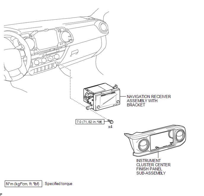
1. REMOVE INSTRUMENT CLUSTER CENTER FINISH PANEL SUB-ASSEMBLY
(See page .gif) )
)
2. REMOVE NAVIGATION RECEIVER ASSEMBLY WITH BRACKET
|
(a) Remove the 4 bolts. |
|
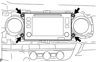
(b) Disconnect the connectors to remove the navigation receiver assembly with bracket.
3. REMOVE NO. 1 NAVIGATION WIRE (w/ Satellite Radio)
(See page )
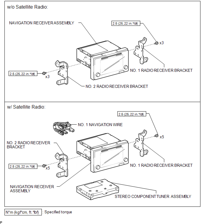
4. REMOVE NO. 1 RADIO RECEIVER BRACKET
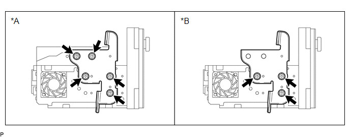 Text in Illustration
|
*A |
w/ Satellite Radio |
*B |
w/o Satellite Radio |
(a) w/ Satellite Radio:
Remove the 5 bolts and No. 1 radio receiver bracket.
(b) w/o Satellite Radio:
Remove the 3 bolts and No. 1 radio receiver bracket.
5. REMOVE NO. 2 RADIO RECEIVER BRACKET
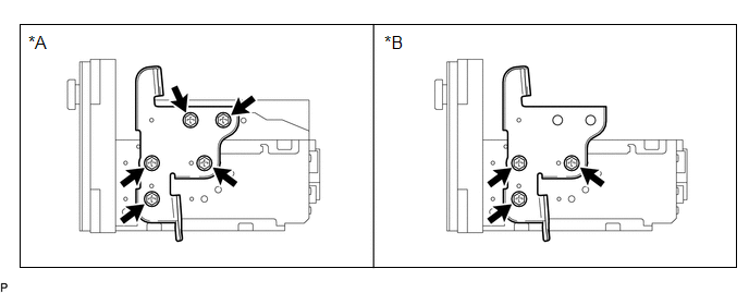 Text in Illustration
|
*A |
w/ Satellite Radio |
*B |
w/o Satellite Radio |
(a) w/ Satellite Radio:
Remove the 5 bolts and No. 2 radio receiver bracket.
(b) w/o Satellite Radio:
Remove the 3 bolts and No. 2 radio receiver bracket.
6. REMOVE STEREO COMPONENT TUNER ASSEMBLY (w/ Satellite Radio)
(See page )
Installation
INSTALLATION
PROCEDURE
1. INSTALL STEREO COMPONENT TUNER ASSEMBLY (w/ Satellite Radio)
(See page .gif) )
)
2. INSTALL NO. 2 RADIO RECEIVER BRACKET
(a) w/o Satellite Radio:
Install the No. 2 radio receiver bracket with the 3 bolts.
Torque:
2.5 N·m {25 kgf·cm, 22 in·lbf}
(b) w/ Satellite Radio:
Install the No. 2 radio receiver bracket with the 5 bolts.
Torque:
2.5 N·m {25 kgf·cm, 22 in·lbf}
3. INSTALL NO. 1 RADIO RECEIVER BRACKET
(a) w/o Satellite Radio:
Install the No. 1 radio receiver bracket with the 3 bolts.
Torque:
2.5 N·m {25 kgf·cm, 22 in·lbf}
(b) w/ Satellite Radio:
Install the No. 1 radio receiver bracket with the 5 bolts.
Torque:
2.5 N·m {25 kgf·cm, 22 in·lbf}
4. INSTALL NO. 1 NAVIGATION WIRE (w/ Satellite Radio)
(See page )
5. INSTALL NAVIGATION RECEIVER ASSEMBLY WITH BRACKET
(a) Connect the connectors.
(b) Install the navigation receiver assembly with bracket with the 4 bolts.
Torque:
7.0 N·m {71 kgf·cm, 62 in·lbf}
6. INSTALL INSTRUMENT CLUSTER CENTER FINISH PANEL SUB-ASSEMBLY
(See page )
 Navigation Antenna
Components
COMPONENTS
ILLUSTRATION
Installation
INSTALLATION
PROCEDURE
1. INSTALL NAVIGATION ANTENNA ASSEMBLY
(a) Install the navigation antenna assembly with the 2 screws.
(b) Engage th ...

Other materials:
Transmission Range Sensor Circuit Malfunction (PRNDL Input) (P0705)
DESCRIPTION
The park/neutral position switch detects the shift lever position and sends signals
to the ECM.
DTC No.
DTC Detection Condition
Trouble Area
P0705
One of the following conditions is met:
(A) Any 2 or more of the followin ...
Air Conditioning Compressor Magnetic Clutch Circuit
DESCRIPTION
When the air conditioning amplifier assembly is turned on, a magnetic clutch
on signal is sent from the MGC terminal of the air conditioning amplifier assembly.
Then, the MG CLT relay turns on to operate the magnetic clutch assembly.
WIRING DIAGRAM
CAUTION / NOTICE / HINT
NO ...
Installation
INSTALLATION
PROCEDURE
1. INSTALL CHILD RESTRAINT SEAT ANCHOR BRACKET SUB-ASSEMBLY
HINT:
Use the same procedure for the side.
(a) Install the child restraint seat anchor bracket sub-assembly with the 2 bolts.
Torque:
30 N·m {306 kgf·cm, 22 ft·lbf}
(b) Reinstall the floor carpet.
2. INST ...
