Toyota Tacoma (2005–2015) Owners Manual: Downhill Assist Control system
The downhill assist control system helps to prevent excessive speed on steep downhill descents.
■ System operation
The system will operate when the vehicle is traveling under 15 mph (25 km/h) and the front-wheel drive control switch is in the L4 position.
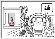
Press the DAC switch. The indicator will come on, and the system will operate.
With the vehicle traveling at a speed of 15 mph (25 km/h) or less, release your foot from the accelerator or brake pedal to activate the system.
When the system is in operation, the slip indicator will flash, and the stop lights/high mounted stop light will come on. A sound may also occur during the operation. This does not indicate a malfunction.
■ Turning off the system
Press the DAC switch while the system is in operation. The indicator will flash as the system gradually ceases operation, and will turn off when the system is fully off.
Pressing the DAC switch while the indicator is flashing will start the system again.
■Operating tips
The system will operate when the shift lever is in a position other than P.
However, to make effective use of the system it is recommended that the shift lever be shifted to 2 or L.
■The system will not operate when
●The front-wheel drive control switch is in the H2 or H4 position.
●The rear differential is locked.
■The downhill assist control system indicator light flashes when
●The shift lever is in the N position.
●The front-wheel drive control switch is in the H2 or H4 position.
●The rear differential is locked.
■If the brake system overheats
The system will cease operation and a buzzer will sound to alert the driver.
Stop the vehicle in a safe place. (There is no problem with continuing normal driving.)
■System malfunction
●The downhill assist control system indicator does not come on when the engine switch is turned to the ON position.
●The downhill assist control system indicator does not come on when the DAC switch is pressed.
In the above cases have your vehicle checked by your Toyota dealer.
CAUTION
■Do not rely excessively on the downhill assist control system
It may not be able to maintain a low speed over road surfaces on which sliding can easily occur, such as extremely steep slopes or icy or muddy roads.
 Rear differential lock system
The rear differential lock system is provided for use only when wheel spinning
occurs in a ditch or on a slippery or rugged surface.
The rear differential lock system is effective in case one of th ...
 Clutch start cancel switch
The switch allows the vehicle to be driven out of difficult situations by cranking
the engine with the clutch engaged.
Never use the switch for normal engine starting. Be sure to follow the startin ...
Other materials:
Front Crankshaft Oil Seal
Components
COMPONENTS
ILLUSTRATION
Installation
INSTALLATION
PROCEDURE
1. INSTALL TIMING GEAR CASE OR TIMING CHAIN CASE OIL SEAL
(a) Apply MP grease to the lip of a new timing gear case or timing chain case
oil seal.
(b) Using SST and a hammer, tap in the timing gear case ...
Confirm Cellular Phone Functionality
PROCEDURE
1.
CHECK CUSTOMER'S CELLULAR PHONE COMPATIBILITY
(a) Check if the cellular phone is compatible (Refer to http://www.toyota.com/entune/).
Result
Result
Proceed to
Cellular phone is compatible
A
...
Diagnostic Trouble Code Chart
DIAGNOSTIC TROUBLE CODE CHART
If a DTC is displayed during the DTC check, check the parts listed in
the table below and proceed to the "See page" given.
*1: "Comes on" means the Malfunction Indicator Lamp (MIL) illuminates.
*2: "DTC stored" means ...
