Toyota Tacoma (2015-2018) Service Manual: Manual Transmission Oil
Components
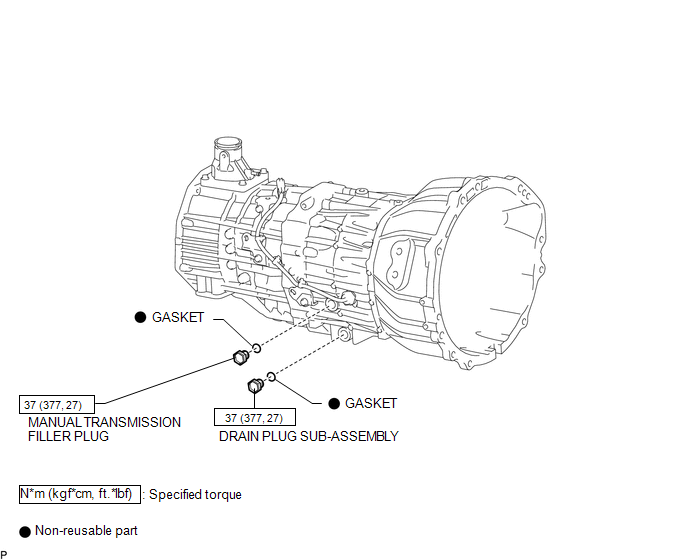
COMPONENTS
ILLUSTRATION
On-vehicle Inspection
ON-VEHICLE INSPECTION
PROCEDURE
1. INSPECT MANUAL TRANSMISSION OIL
(a) Park the vehicle on a level surface.
(b) Remove the transmission filler plug and gasket.
|
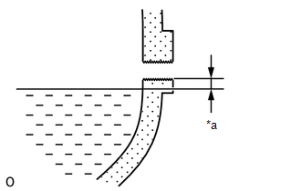
(c) Check that the oil level is between 0 to 5 mm (0 to 0.196 in.) from the bottom lip of the filler plug opening. Text in Illustration
If the result is not as specified, add transmission oil. Manual transmission oil:
NOTICE:
|
|
(d) Inspect for oil leaks when the oil level is low.
(e) Install a new gasket and the transmission filler plug.
Torque:
37 N·m {377 kgf·cm, 27 ft·lbf}
Replacement
REPLACEMENT
PROCEDURE
1. DRAIN MANUAL TRANSMISSION OIL
(a) Remove the manual transmission filler plug and gasket.
(b) Remove the drain plug sub-assembly and gasket and then drain the manual transmission oil.
(c) Install a new gasket and the drain plug sub-assembly.
Torque:
37 N·m {377 kgf·cm, 27 ft·lbf}
2. ADD MANUAL TRANSMISSION OIL
|
(a) Add manual transmission oil until the oil level is within 0 to 5 mm (0 to 0.196 in.) from the bottom lip of the manual transmission filler plug opening. Text in Illustration
Manual transmission oil:
|
|
.png)
3. INSPECT MANUAL TRANSMISSION OIL
.gif)
 Removal
REMOVAL
PROCEDURE
1. PRECAUTION
NOTICE:
After turning the ignition switch off, waiting time may be required before disconnecting
the cable from the negative (-) battery terminal. Therefore, make ...

Other materials:
Low Pitched Horn
Components
COMPONENTS
ILLUSTRATION
Inspection
INSPECTION
PROCEDURE
1. INSPECT LOW PITCHED HORN ASSEMBLY
(a) Check the operation.
(1) Apply battery voltage to the terminal 1 and body ground, and check
that the low pitched horn assembly sounds.
Text in Illustration
...
Wireless Charger Illumination Circuit
DESCRIPTION
When the light control switch is turned to the tail or head position, this circuit
sends an illumination signal to the mobile wireless charger cradle assembly. Based
on this signal, the mobile wireless charger cradle assembly dims the indicator lights
(green and amber).
WIRING DI ...
Diagnostic Trouble Code Chart
DIAGNOSTIC TROUBLE CODE CHART
HINT:
If a trouble code is output during the DTC check, inspect the trouble areas listed
for that code. For details of the code, refer to "See page" in the DTC chart.
Wireless Door Lock Control System
DTC Code
Detection Item
...
