Toyota Tacoma (2015-2018) Service Manual: Main Switch Power Source Circuit
DESCRIPTION
This circuit supplies power to the wireless charger main switch (mobile wireless charger switch) and illuminates the switch indicator light when the wireless charger main switch (mobile wireless charger switch) is turned on.
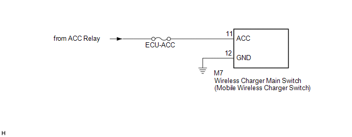
WIRING DIAGRAM
CAUTION / NOTICE / HINT
NOTICE:
Inspect the fuses for circuits related to this system before performing the following inspection procedure.
PROCEDURE
|
1. |
CHECK HARNESS AND CONNECTOR (WIRELESS CHARGER MAIN SWITCH (MOBILE WIRELESS CHARGER SWITCH) POWER SOURCE) |
(a) Disconnect the M7 wireless charger main switch (mobile wireless charger switch) connector.
(b) Measure the resistance according to the value(s) in the table below.
Standard Resistance:
|
Tester Connection |
Condition |
Specified Condition |
|---|---|---|
|
M7-12 (GND) - Body ground |
Always |
Below 1 Ω |
|
M7-11 (ACC) - Body ground |
Always |
10 kΩ or higher |
(c) Measure the voltage according to the value(s) in the table below.
Standard Voltage:
|
Tester Connection |
Switch Condition |
Specified Condition |
|---|---|---|
|
M7-11 (ACC) - M7-12 (GND) |
Ignition switch ACC |
11 to 14 V |
| OK | .gif) |
PROCEED TO NEXT SUSPECTED AREA SHOWN IN PROBLEM SYMPTOMS TABLE |
| NG | |
REPAIR OR REPLACE HARNESS OR CONNECTOR |
 Problem Symptoms Table
PROBLEM SYMPTOMS TABLE
HINT:
Use the table below to help determine the cause of problem symptoms.
If multiple suspected areas are listed, the potential causes of the symptoms
are lis ...
 Terminals Of Ecu
TERMINALS OF ECU
1. MOBILE WIRELESS CHARGER CRADLE ASSEMBLY
Tester Connection
Wiring Color
Terminal Description
Condition
Specified Condition ...
Other materials:
Transmitter ID not Registered (C2171/71)
DESCRIPTION
The IDs of each tire pressure warning valve and transmitter are registered to
the tire pressure warning ECU and receiver.
When the ECU detects that a transmitter ID code is not registered in the ECU,
this DTC is stored.
DTC No.
Detection Item
DTC D ...
Inspection
INSPECTION
PROCEDURE
1. INSPECT HAZARD WARNING SIGNAL SWITCH ASSEMBLY (AIR CONDITIONING CONTROL ASSEMBLY)
(a) Check the resistance.
(1) Measure the resistance according to the value(s) in the table below.
Text in Illustration
*a
Component withou ...
Parts Location
PARTS LOCATION
ILLUSTRATION
*1
FUEL TANK CAP ASSEMBLY
*2
CHARCOAL CANISTER ASSEMBLY
*3
CHARCOAL CANISTER LEAK DETECTION PUMP SUB-ASSEMBLY
*4
PCV VALVE
*5
PURGE VSV
...
