Toyota Tacoma (2015-2018) Service Manual: USB Audio System Recognition/Play Error
DESCRIPTION
When a USB device or "iPod" is connected to the USB jack of the No. 1 stereo jack adapter assembly, it must have playable files. The device must also communicate with and be recognized by the navigation receiver assembly. This diagnosis procedure is for when a device is not recognized, or files from the device cannot be played normally.
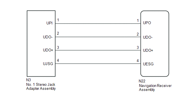
WIRING DIAGRAM
CAUTION / NOTICE / HINT
HINT:
- When a large amount of data is in a USB device, it may take a while to begin play.
- When using a USB device, files that are protected by copy protection cannot be played.
- When files are not played in the sorted order, perform the following
procedure before inspection.
- Add numbers in front of the file names.
- Put the files in a folder and copy the folder data to the USB device.
PROCEDURE
|
1. |
CHECK USB DEVICE OR "iPod" |
(a) Disconnect the USB device or "iPod" from the No. 1 stereo jack adapter assembly.
(b) Check if playable files are present on the USB device or "iPod".
HINT:
Refer to System Description for playable files (See page
.gif) ).
).
(c) Check if the USB device is a compatible format or "iPod" is a compatible version.
HINT:
Refer to System Description for compatible formats and versions (See page
).
|
Result |
Proceed to |
|---|---|
|
No playable files exist, or incompatible device format or version |
A |
|
Playable files exist, and compatible device format or version |
B |
| A | .gif) |
USB DEVICE FORMAT WAS INCOMPATIBLE, "iPod" VERSION WAS INCOMPATIBLE, OR NO PLAYABLE FILES PRESENT |
|
.gif)
|
2. |
CHECK HARNESS AND CONNECTOR (NAVIGATION RECEIVER ASSEMBLY - NO. 1 STEREO JACK ADAPTER ASSEMBLY) |
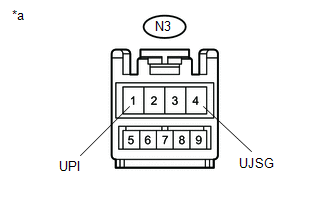
(a) Disconnect the N3 No. 1 stereo jack adapter assembly connector.
(b) Disconnect the N22 navigation receiver assembly connector.
(c) Measure the resistance according to the value(s) in the table below.
Standard Resistance:
|
Tester Connection |
Condition |
Specified Condition |
|---|---|---|
|
N3-1 (UPI) - N22-1 (UPO) |
Always |
Below 1 Ω |
|
N3-2 (UDO-) - N22-2 (UDO-) |
Always |
Below 1 Ω |
|
N3-3 (UDO+) - N22-3 (UDO+) |
Always |
Below 1 Ω |
|
N3-4 (UJSG) - N22-4 (UESG) |
Always |
Below 1 Ω |
|
N3-1 (UPI) - Body ground |
Always |
10 kΩ or higher |
|
N3-2 (UDO-) - Body ground |
Always |
10 kΩ or higher |
|
N3-3 (UDO+) - Body ground |
Always |
10 kΩ or higher |
|
N3-4 (UJSG) - Body ground |
Always |
10 kΩ or higher |
| NG | |
REPAIR OR REPLACE HARNESS OR CONNECTOR |
|
|
3. |
INSPECT NAVIGATION RECEIVER ASSEMBLY (NO. 1 STEREO JACK ADAPTER ASSEMBLY POWER SOURCE) |
(a) Reconnect the N22 navigation receiver assembly connector.
|
(b) Measure the voltage according to the value(s) in the table below. Standard Voltage:
|
|
| NG | |
REPLACE NAVIGATION RECEIVER ASSEMBLY |
|
|
4. |
FORMAT USB DEVICE OR RESTORE "iPod" AND RECHECK |
(a) Delete all files in the USB device or "iPod" and format/restore it.
(b) Save the data again and check if it can be played on the in-vehicle device.
NOTICE:
Formatting a USB device or restoring an "iPod" erases all music on the device. Ensure that backup music data is available before performing this operation.
OK:
Malfunction disappears.
| OK | |
END |
|
|
5. |
REPLACE USB DEVICE OR "iPod" |
(a) Turn the ignition switch off.
HINT:
When one of these DTCs has been stored, it is necessary to turn off the ignition switch to make it possible for the vehicle to recognize a new device when it is connected.
(b) Turn the ignition switch to ACC.
(c) Connect a known good USB device or "iPod" to the No. 1 stereo jack adapter assembly.
HINT:
- If the malfunction occurred when a USB device was in use, use another USB device for the inspection. If the malfunction occurred when an "iPod" was in use, use another "iPod" for the inspection.
- Refer to System Description for compatible formats and versions (See
page ).
|
|
6. |
CHECK USB DEVICE OR "iPod" |
(a) Check if a USB device or "iPod" is recognized by the navigation receiver assembly, and if information such as track, artist and album names are displayed on the screen.
OK:
Malfunction disappears.
| OK | |
USB DEVICE OR "iPod" WAS INCOMPATIBLE OR DEFECTIVE |
| NG | |
PROCEED TO NEXT SUSPECTED AREA SHOWN IN PROBLEM SYMPTOMS TABLE |
 Portable Player cannot be Registered
CAUTION / NOTICE / HINT
HINT:
Some versions of "Bluetooth" compatible audio players may not function, or the
function may be limited using the navigation receiver assembly, even if the p ...
 Black Screen
PROCEDURE
1.
CHECK DISPLAY SETTING
(a) Check that the display is not in "Screen Off" mode.
OK:
The display setting is not in "Screen Off" mode. ...
Other materials:
Dtc Check / Clear
DTC CHECK / CLEAR
NOTICE:
When using the Techstream with the engine switch off, connect the Techstream
to the DLC3 and turn a courtesy light switch on and off at intervals of 1.5 seconds
or less until communication between the Techstream and the vehicle begins. Then
select the vehicle type u ...
Portable Player cannot be Connected Manually/Automatically
CAUTION / NOTICE / HINT
HINT:
Some versions of "Bluetooth" compatible audio players may not function, or the
function may be limited using the radio and display receiver assembly, even if the
portable audio player itself can play files (See page
).
PROCEDURE
1.
...
Disposal
DISPOSAL
CAUTION / NOTICE / HINT
CAUTION:
Before performing pre-disposal deployment of any SRS part, review and closely
follow all applicable environmental and hazardous material regulations. Pre-disposal
deployment may be considered hazardous material treatment.
PROCEDURE
1. PRECAUTION
...
