Toyota Tacoma (2015-2018) Service Manual: License Plate Light Assembly
Components
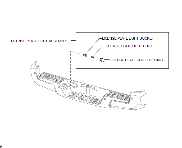
COMPONENTS
ILLUSTRATION
Removal
REMOVAL
CAUTION / NOTICE / HINT
HINT:
- Use the same procedure for both the LH and RH sides.
- The procedure described below is for the LH side.
PROCEDURE
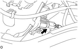
1. REMOVE LICENSE PLATE LIGHT ASSEMBLY
|
(a) Disconnect the connector. |
|
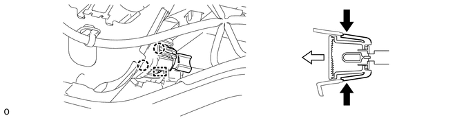
(b) Disengage the 2 claws and guide to remove the license plate light assembly.
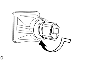
2. REMOVE LICENSE PLATE LIGHT BULB
|
(a) Turn the license plate light socket with the license plate light bulb in the direction indicated by the arrow shown in the illustration to remove them. |
|
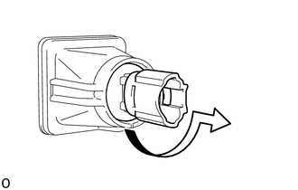
(b) Remove the license plate light bulb from the license plate light socket.
Installation
INSTALLATION
CAUTION / NOTICE / HINT
HINT:
- Use the same procedure for both the LH and RH sides.
- The procedure described below is for the LH side.
PROCEDURE
1. INSTALL LICENSE PLATE LIGHT BULB
(a) Install the license plate light bulb to the license plate light socket.
|
(b) Turn the license plate light socket with the license plate light bulb in the direction indicated by the arrow shown in the illustration to install them. |
|
2. INSTALL LICENSE PLATE LIGHT ASSEMBLY
(a) Engage the guide and 2 claws to install the license plate light assembly.
 Interior Illumination Light
Components
COMPONENTS
ILLUSTRATION
Removal
REMOVAL
PROCEDURE
1. REMOVE INSTRUMENT PANEL LOWER CENTER FINISH PANEL
(See page )
2. REMOVE NO. 1 INTERIOR ILLUMINATION LIGHT ASSEMBLY
...
 Lighting System
...
Other materials:
Engine Immobiliser System Signal (Some Circuit Quantity, Reported via Serial
Data) Invalid (B279986)
DESCRIPTION
When there are communication malfunctions between the ECM and certification ECU
(smart key ECU assembly), or when the communication ID codes do not match, the ECM
stores this DTC.
DTC Code
DTC Detection Condition
Trouble Area
DTC Output C ...
Freeze Frame Data
FREEZE FRAME DATA
1. FREEZE FRAME DATA
HINT:
Whenever a DTC is detected or the ABS operates, the skid control ECU
stores the current vehicle (sensor) state as freeze frame data.
The skid control ECU stores the number of times (maximum: 31) the ignition
switch has been turned f ...
Removal
REMOVAL
CAUTION / NOTICE / HINT
HINT:
Use the same procedure for both the RH and LH sides.
The procedure described below is for the LH side.
PROCEDURE
1. PRECAUTION
NOTICE:
After turning the ignition switch off, waiting time may be required before disconnecting
the cable f ...
