Toyota Tacoma (2015-2018) Service Manual: Interior Illumination Light
Components
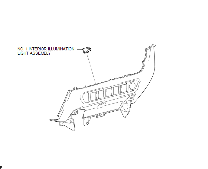
COMPONENTS
ILLUSTRATION
Removal
REMOVAL
PROCEDURE
1. REMOVE INSTRUMENT PANEL LOWER CENTER FINISH PANEL
(See page .gif) )
)
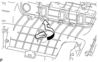
2. REMOVE NO. 1 INTERIOR ILLUMINATION LIGHT ASSEMBLY
|
(a) Turn the No. 1 interior illumination light assembly in the direction indicated by the arrow in the illustration to remove it. |
|
Installation
INSTALLATION
PROCEDURE
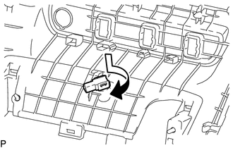
1. INSTALL NO. 1 INTERIOR ILLUMINATION LIGHT ASSEMBLY
|
(a) Turn the No. 1 interior illumination light assembly in the direction indicated by the arrow shown in the illustration to install it. |
|
2. INSTALL INSTRUMENT PANEL LOWER CENTER FINISH PANEL
(See page .gif) )
)
 Installation
INSTALLATION
PROCEDURE
1. INSTALL CENTER STOP LIGHT ASSEMBLY (for Bulb Type Stop Light)
(a) Install the 3 center stop light bulbs to the 3 center stop light sockets.
(b) Turn the 3 cent ...
 License Plate Light Assembly
Components
COMPONENTS
ILLUSTRATION
Removal
REMOVAL
CAUTION / NOTICE / HINT
HINT:
Use the same procedure for both the LH and RH sides.
The procedure described below is for the ...
Other materials:
Lost Communication With ECM/PCM "A" Missing Message (U010087)
DESCRIPTION
The engine control unit and transmission control unit are located inside the
ECM. The engine control unit intercommunicates with the transmission control ECU
via CAN communication. If there is a problem in this intercommunication, the ECM
stores this DTC.
DTC Code
...
Customize Parameters
CUSTOMIZE PARAMETERS
PROCEDURE
1. CUSTOMIZE AIR CONDITIONING SYSTEM
(a) Customizing with the Techstream
NOTICE:
When the customer requests a change in a function, first make sure that
the function can be customized.
Be sure to make a note of the current settings before customizi ...
Removal
REMOVAL
PROCEDURE
1. REMOVE REAR SEAT CUSHION ASSEMBLY
(a) Remove the 2 bolts and rear seat cushion assembly.
2. REMOVE REAR SEATBACK HINGE COVER
(a) Disengage the 6 claws to remove the 2 rear seatback hinge covers.
...
