Toyota Tacoma (2015-2018) Service Manual: Sound Signal Circuit between Radio Receiver and Stereo Component Amplifier
DESCRIPTION
The navigation receiver assembly sends a sound signal to the stereo component amplifier assembly via this circuit.
The sound signal that has been sent is amplified by the stereo component amplifier assembly, and then is sent to the speakers.
If there is an open or short in the circuit, sound cannot be heard from the speakers even if there is no malfunction in the stereo component amplifier assembly or speakers.
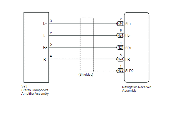
WIRING DIAGRAM
PROCEDURE
|
1. |
CHECK HARNESS AND CONNECTOR (NAVIGATION RECEIVER ASSEMBLY - STEREO COMPONENT AMPLIFIER ASSEMBLY) |
(a) Disconnect the N23 and N24 navigation receiver assembly connector.
(b) Disconnect the S23 stereo component amplifier assembly connector.
(c) Measure the resistance according to the value(s) in the table below.
Standard Resistance:
|
Tester Connection |
Condition |
Specified Condition |
|---|---|---|
|
S23-3 (L+) - N24-2 (FL+) |
Always |
Below 1 Ω |
|
S23-2 (L-) - N24-6 (FL-) |
Always |
Below 1 Ω |
|
S23-5 (R+) - N24-1 (FR+) |
Always |
Below 1 Ω |
|
S23-4 (R-) - N24-5 (FR-) |
Always |
Below 1 Ω |
|
S23-3 (L+) - Body ground |
Always |
10 kΩ or higher |
|
S23-2 (L-) - Body ground |
Always |
10 kΩ or higher |
|
S23-5 (R+) - Body ground |
Always |
10 kΩ or higher |
|
S23-4 (R-) - Body ground |
Always |
10 kΩ or higher |
|
N23-4 (SLD2) - Body ground |
Always |
10 kΩ or higher |
| OK | .gif) |
PROCEED TO NEXT SUSPECTED AREA SHOWN IN PROBLEM SYMPTOMS TABLE |
| NG | |
REPAIR OR REPLACE HARNESS OR CONNECTOR |
 Speaker Circuit
DESCRIPTION
If there is a short in a speaker circuit, the stereo component amplifier assembly*1
or navigation receiver assembly*2 detects it and stops output to the speakers.
Thus sound cannot be ...
 Data Signal Circuit between Stereo Jack Adapter and Extension Module
DESCRIPTION
The No. 1 stereo jack adapter assembly sends the sound data signal or image data
signal from a USB device to the navigation receiver assembly via this circuit.
WIRING DIAGRAM
PROCED ...
Other materials:
Steering Angle Sensor Output Malfunction (C1434)
DESCRIPTION
Steering angle sensor signals are input to the skid control ECU (brake actuator
assembly) via the CAN communication system.
HINT:
When a malfunction occurs in the communication line to the steering angle sensor,
U0126 is output. If a DTC related to the CAN communication line is ou ...
Precaution
PRECAUTION
1. IGNITION SWITCH EXPRESSION
(a) The type of ignition switch used on this model differs depending on the specifications
of the vehicle. The expressions listed in the table below are used in this section.
Expression
Ignition Switch (Position)
Engine S ...
How To Proceed With Troubleshooting
CAUTION / NOTICE / HINT
HINT:
Use this procedure to troubleshoot the seat heater system.
*: Use the Techstream.
PROCEDURE
1.
VEHICLE BROUGHT TO WORKSHOP
NEXT
2.
...
