Toyota Tacoma (2015-2018) Service Manual: Installation
INSTALLATION
PROCEDURE
1. INSTALL CHARCOAL CANISTER LEAK DETECTION PUMP SUB-ASSEMBLY
|
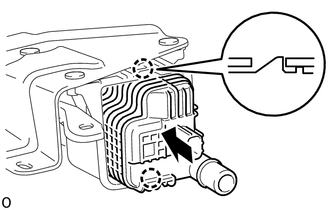
(a) Engage the 2 claws to install a new charcoal canister leak detection pump sub-assembly to the charcoal canister assembly. NOTICE:
|
|
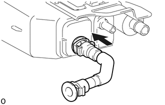
2. CONNECT FUEL TANK VENT HOSE SUB-ASSEMBLY
|
(a) Align the fuel tank vent hose sub-assembly connector with the charcoal canister assembly, then push in the fuel tank vent hose until the retainer makes a "click" sound to connect the fuel tank vent hose sub-assembly. NOTICE:
|
|
3. INSTALL CHARCOAL CANISTER ASSEMBLY
(a) Install the charcoal canister assembly with the bolt and 3 nuts.
Torque:
20 N·m {204 kgf·cm, 15 ft·lbf}
(b) Engage the guide to install the wire harness bracket.
(c) Install the nut.
Torque:
12.5 N·m {127 kgf·cm, 9 ft·lbf}
(d) Engage the clamp to install the wire harness.
(e) Connect the 3 connectors.
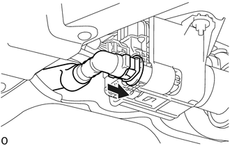
4. CONNECT FUEL TANK VENT HOSE
|
(a) Align the fuel tank vent hose connector with the charcoal canister assembly, then push in the fuel tank vent hose until the retainer makes a "click" sound to connect the fuel tank vent hose to the charcoal canister assembly. NOTICE:
|
|
5. CONNECT CHARCOAL CANISTER FUEL HOSE
(a) Connect the charcoal canister fuel hose with hose clip.
6. INSTALL FUEL TANK ASSEMBLY
Click here .gif)
7. INSPECT FOR FUEL LEAK
Click here
 Inspection
INSPECTION
PROCEDURE
1. INSPECT CHARCOAL CANISTER ASSEMBLY
(a) Visually check the charcoal canister assembly.
(1) Visually check the charcoal canister assembly for cracks or damage.
...

Other materials:
On-vehicle Inspection
ON-VEHICLE INSPECTION
PROCEDURE
1. CHECK FUEL PUMP OPERATION AND INSPECT FOR FUEL LEAK
(a) Connect the Techstream to the DLC3.
(1) Turn the ignition switch to ON.
NOTICE:
Do not start the engine.
(2) Turn the Techstream on.
(3) Enter the following menus: Powertrain / Engine / Active Test / C ...
Disassembly
DISASSEMBLY
CAUTION / NOTICE / HINT
CAUTION:
Wear protective gloves. Sharp areas on the parts may injure your hands.
PROCEDURE
1. REMOVE REAR SEAT CUSHION BAND
(a) Remove the screw and rear seat cushion band.
2. REMOVE REAR SEAT HEADREST HO ...
Diagnosis System
DIAGNOSIS SYSTEM
1. DESCRIPTION
(a) Blind spot monitor data and Diagnostic Trouble Codes (DTCs) can be read from
the Data Link Connector 3 (DLC3) of the vehicle. When the system seems to be malfunctioning,
use the Techstream to check for malfunctions and to repair it.
2. CHECK DLC3
(a) Check ...
