Toyota Tacoma (2015-2018) Service Manual: Inspection
INSPECTION
PROCEDURE
1. INSPECT CHARCOAL CANISTER ASSEMBLY
|
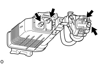
(a) Visually check the charcoal canister assembly. (1) Visually check the charcoal canister assembly for cracks or damage. If cracks or damage are found, replace the charcoal canister assembly. |
|
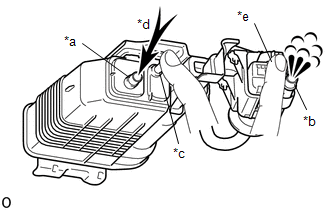
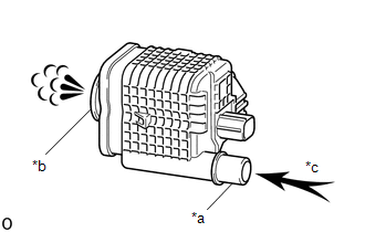
(b) Check charcoal canister assembly operation.
|
*a |
Vent Port |
|
*b |
Air Inlet Port |
|
*c |
Purge Port |
|
*d |
Air |
|
*e |
Leak Detection Pump Sub-assembly Connector |
(1) With the purge port and leak detection pump sub-assembly connector closed, blow 5 kPa (0.05 kgf/cm2, 0.7 psi) of air into the vent port, and check that air flows from the air inlet port.
If the result is not as specified, replace the charcoal canister assembly.
|
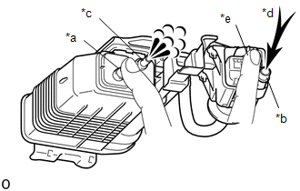
(2) With the vent port and leak detection pump sub-assembly connector closed, blow 5 kPa (0.05 kgf/cm2, 0.7 psi) of air into the air inlet port, and check that air flows from the purge port. If the result is not as specified, replace the charcoal canister assembly. |
|
|
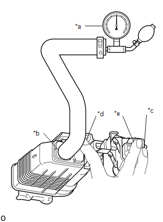
(c) Check for air leaks. (1) Connect a pressure gauge to the vent port of the charcoal canister. (2) With the purge port, air inlet port and leak detection pump sub-assembly connector closed, apply 20 kPa (150 mmHg, 5.91 in.Hg) of pressurized air into the vent port, then confirm that pressure is retained for 1 minute. If the result is not as specified, replace the charcoal canister assembly. |
|
2. INSPECT CHARCOAL CANISTER LEAK DETECTION PUMP SUB-ASSEMBLY
(a) Check the charcoal canister leak detection pump sub-assembly.
|
*a |
Port A |
|
*b |
Port B |
|
*c |
Air |
(1) Check that air flows from port A to port B.
If the result is not as specified, replace the charcoal canister leak detection pump sub-assembly.
|
(2) Connect the positive (+) lead of the battery to terminal 5 and the negative (-) lead to terminal 1. |
|
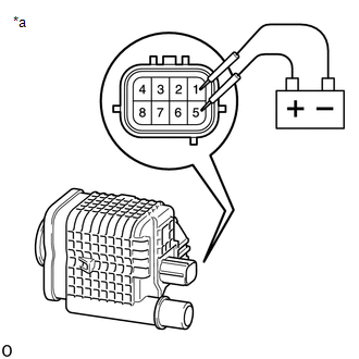
(3) Check that a clicking sound is heard from the leak detection pump sub-assembly.
If the result is not as specified, replace the charcoal canister leak detection pump sub-assembly.
 Removal
REMOVAL
PROCEDURE
1. REMOVE FUEL TANK ASSEMBLY
Click here
2. DISCONNECT CHARCOAL CANISTER FUEL HOSE
(a) Loosen the hose clip and disconnect the charcoal canister fuel hose.
...
 Installation
INSTALLATION
PROCEDURE
1. INSTALL CHARCOAL CANISTER LEAK DETECTION PUMP SUB-ASSEMBLY
(a) Engage the 2 claws to install a new charcoal canister leak detection
pump sub-assembly to the ...
Other materials:
How To Proceed With Troubleshooting
PROCEDURE
1.
CHECK TIRE AND WHEEL SYSTEM
DIAGNOSIS OF IRREGULAR TIRE WEAR
GO TO STEP 11
DIAGNOSIS OF TIRE VIBRATION
2.
TIGHTEN WHEEL NUTS
...
Parts Location
PARTS LOCATION
ILLUSTRATION
*A
for Automatic Transmission
-
-
*1
FRONT SPEED SENSOR LH
*2
FRONT SPEED SENSOR RH
*3
FRONT AXLE WITH ABS ROTOR BEARING ASSEMBLY LH
- FRONT SP ...
Removal
REMOVAL
PROCEDURE
1. REMOVE AIR CONDITIONING CONTROL ASSEMBLY (for Automatic Air Conditioning System)
Click here
2. REMOVE AIR CONDITIONING CONTROL ASSEMBLY (for Manual Air Conditioning System)
Click here
3. REMOVE LOWER NO. 2 INSTRUMENT PANEL AIRBAG ASSEMBLY
Click here
4. REMOVE INSTR ...
