Toyota Tacoma (2015-2018) Service Manual: Installation
INSTALLATION
PROCEDURE
1. INSTALL REAR BRAKE DRUM SUB-ASSEMBLY
(a) Install a new drum gasket onto the rear brake drum.
(b) Install the rear brake drum.
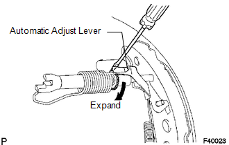
2. ADJUST REAR DRUM BRAKE SHOE CLEARANCE
(a) Provisionally install the hub nuts.
(b) Remove the hole plug, and turn the adjuster to expand the shoe until the drum locks.
(c) Using a screwdriver, release the adjuster 15 notches.
(d) Install the hole plug.
3. FILL RESERVOIR WITH BRAKE FLUID (for Hydraulic Brake Booster)
.gif)
4. FILL RESERVOIR WITH BRAKE FLUID (for Vacuum Brake Booster)
5. BLEED BRAKE BOOSTER WITH ACCUMULATOR PUMP ASSEMBLY (for Hydraulic Brake Booster)
6. BLEED MASTER CYLINDER (for Vacuum Brake Booster)
7. BLEED BRAKE LINE (for Hydraulic Brake Booster)
8. BLEED BRAKE LINE (for Vacuum Brake Booster)
9. BLEED MASTER CYLINDER SOLENOID (for Hydraulic Brake Booster)
10. BLEED BRAKE ACTUATOR (for Vacuum Brake Booster)
11. INSPECT FLUID LEVEL IN RESERVOIR (for Hydraulic Brake Booster)
12. INSPECT FLUID LEVEL IN RESERVOIR (for Vacuum Brake Booster)
13. INSPECT FOR BRAKE FLUID LEAK
14. INSTALL REAR WHEEL
Torque:
113 N·m {1152 kgf·cm, 83 ft·lbf}
15. INSPECT PARKING BRAKE PEDAL TRAVEL
16. ADJUST PARKING BRAKE PEDAL TRAVEL
 Reassembly
REASSEMBLY
PROCEDURE
1. INSTALL REAR WHEEL CYLINDER CUP KIT
(a) Provisionally tighten the bleeder plug to the rear wheel brake cylinder,
and install the bleeder plug cap.
(b) Apply lithium soa ...
 Vacuum Pump
Components
COMPONENTS
ILLUSTRATION
Installation
INSTALLATION
PROCEDURE
1. INSTALL VACUUM PUMP ASSEMBLY
(a) Apply engine oil to the 2 O-rings on the vacuum pump assembly.
(b) Apply engine ...
Other materials:
Blind Spot Monitor Sensor Communication Stop Mode
DESCRIPTION
Detection Item
Symptom
Trouble Area
Blind Spot Monitor Sensor Communication Stop Mode
Either Condition is met:
Communication stop for "Blind Spot Monitor Master" is indicated
on the "Communic ...
Inspection
INSPECTION
PROCEDURE
1. INSPECT BRAKE DRUM INSIDE DIAMETER
(a) Using a brake drum gauge or equivalent, measure the inside diameter of the
drum.
Standard inside diameter:
254 mm (10.00 in.)
Maximum inside diameter:
256 mm (10.08 in.)
If the inside diameter is greater than the maximum, r ...
TS and CG Terminal Circuit
DESCRIPTION
In Test Mode (signal check), a malfunction in the speed sensor that cannot be
detected when the vehicle is stopped can be detected while driving.
Sensor check mode can be entered by connecting terminals TS and CG of the DLC3
and turning the ignition switch from off to ON.
WIRING D ...
