Toyota Tacoma (2015-2018) Service Manual: Installation
INSTALLATION
PROCEDURE
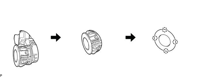
1. INSTALL NO. 1 ULTRASONIC SENSOR
HINT:
Use the same procedure for both sides.
(a) Engage the 4 claws to install the 4 No. 1 ultrasonic sensors as shown in the illustration.
2. INSTALL REAR BUMPER EXTENSION LH (w/ Towing Package)
(See page .gif) )
)
3. INSTALL REAR BUMPER EXTENSION LH (w/o Towing Package)
(See page )
4. INSTALL REAR BUMPER EXTENSION RH (w/ Towing Package)
HINT:
Use the same procedure as for the LH side.
5. INSTALL REAR BUMPER EXTENSION RH (w/o Towing Package)
HINT:
Use the same procedure as for the LH side.
6. INSTALL REAR BUMPER PAD SUB-ASSEMBLY (w/ Towing Package)
(See page )
7. INSTALL REAR BUMPER PAD SUB-ASSEMBLY (w/o Towing Package)
(See page )
8. INSTALL CONNECTOR COVER (w/ Towing Package)
(See page )
9. INSTALL REAR BUMPER HOLE COVER (w/o Towing Package)
(See page )
10. INSTALL REAR BUMPER ASSEMBLY (w/ Towing Package)
(See page )
11. INSTALL REAR BUMPER ASSEMBLY (w/o Towing Package)
(See page )
 Removal
REMOVAL
PROCEDURE
1. REMOVE REAR BUMPER ASSEMBLY (w/ Towing Package)
(See page )
2. REMOVE REAR BUMPER ASSEMBLY (w/o Towing Package)
(See page )
3. REMOVE CONNECTOR COVER (w/ Towing Package) ...
 Brake
Brake
...
Other materials:
Display does not Dim when Light Control Switch is Turned ON
PROCEDURE
1.
CHECK IMAGE QUALITY SETTING
(a) Display the "Display" screen.
(b) Turn the light control switch to the tail or head position.
(c) Check if "Day Mode" on the display adjustment screen is on.
OK:
"Day Mode" setting is of ...
Installation
INSTALLATION
PROCEDURE
1. INSTALL OIL COOLER ASSEMBLY (w/ Air Cooled Transmission Oil Cooler)
(a) Install the 2 oil cooler brackets to the oil cooler assembly with the 2 bolts.
Torque:
5.5 N·m {56 kgf·cm, 49 in·lbf}
(b) Install the oil cooler assembly to the vehicle body with th ...
Rear seats (Access Cab and Double Cab models)
Access Cab models
The bottom cushion of the rear seats can be raised and lowered.
■ Before raising the bottom cushion
Stow the seat belt buckles.
This prevents the seat belt buckles from falling out when you fold the seatback.
■ Raising the bottom cushion
Raise the bottom cushi ...
