Toyota Tacoma (2015-2018) Service Manual: Removal
REMOVAL
PROCEDURE
1. REMOVE REAR BUMPER ASSEMBLY (w/ Towing Package)
(See page .gif) )
)
2. REMOVE REAR BUMPER ASSEMBLY (w/o Towing Package)
(See page )
3. REMOVE CONNECTOR COVER (w/ Towing Package)
(See page )
4. REMOVE REAR BUMPER HOLE COVER (w/o Towing Package)
(See page )
5. REMOVE REAR BUMPER PAD SUB-ASSEMBLY (w/ Towing Package)
(See page )
6. REMOVE REAR BUMPER PAD SUB-ASSEMBLY (w/o Towing Package)
(See page )
7. REMOVE REAR BUMPER EXTENSION LH (w/ Towing Package)
(See page )
8. REMOVE REAR BUMPER EXTENSION LH (w/o Towing Package)
(See page )
9. REMOVE REAR BUMPER EXTENSION RH (w/ Towing Package)
HINT:
Use the same procedure as for the LH side.
10. REMOVE REAR BUMPER EXTENSION RH (w/o Towing Package)
HINT:
Use the same procedure as for the LH side.
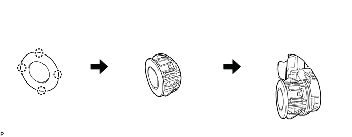
11. REMOVE NO. 1 ULTRASONIC SENSOR
HINT:
Use the same procedure for both sides.
(a) Disengage the 4 claws to remove the 4 No. 1 ultrasonic sensors as shown in the illustration.
 Inspection
INSPECTION
PROCEDURE
1. INSPECT NO. 1 ULTRASONIC SENSOR
(a) Measure the resistance according to the value(s) in the table below.
Text in Illustration
*a
...
 Installation
INSTALLATION
PROCEDURE
1. INSTALL NO. 1 ULTRASONIC SENSOR
HINT:
Use the same procedure for both sides.
(a) Engage the 4 claws to install the 4 No. 1 ultrasonic sensors as shown in
the illustrat ...
Other materials:
Installation
INSTALLATION
CAUTION / NOTICE / HINT
CAUTION:
Some of these service operations affect the SRS airbag system. Read the precautionary
notices concerning the SRS airbag system before servicing.
Click here
PROCEDURE
1. INSTALL FRONT SEAT INNER BELT ASSEMBLY
(a) for Driver Side:
(1) Install t ...
Automatic Disconnecting Differential Motor Limit Switch Circuit (P17A4)
DESCRIPTION
When the A.D.D. actuator switches between 2WD and 4WD, the DL1 and DL2 terminals
of the limit switch and ADD terminal of the A.D.D. position switch change to one
of the following ON/OFF combinations listed in the table below.
Terminal
In 2WD
Switchi ...
Control Module Communication Bus OFF (U0073,U0100,U0114,U0123,U0124,U0126)
DESCRIPTION
The skid control ECU (master cylinder solenoid) receives the signals from the
ECM, steering angle sensor (spiral cable with sensor sub-assembly), 4 wheel drive
control ECU*, and yaw rate and acceleration sensor (airbag sensor assembly) via
the CAN communication system.
*: ...
