Toyota Tacoma (2015-2018) Service Manual: Installation
INSTALLATION
CAUTION / NOTICE / HINT
HINT:
- Use the same procedure for both the RH and LH sides.
- The procedure described below is for the LH side.
PROCEDURE
1. INSTALL CURTAIN SHIELD AIRBAG ASSEMBLY
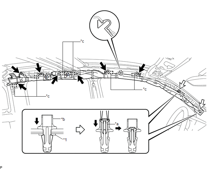
(a) Insert the 6 hooks, install 7 new bolts, 2 new clips (A) with pins and 2 new spacers, and engage 2 clips (B) to install the curtain shield airbag assembly.
 Text in Illustration
|
*1 |
Spacer |
- |
- |
|
*a |
Pin |
*b |
Clip (A) |
|
*c |
Hook |
- |
- |
Torque:
12.5 N·m {127 kgf·cm, 9 ft·lbf}
NOTICE:
Do not twist the curtain shield airbag assembly.
|
(b) Connect the airbag connector to the curtain shield airbag assembly. NOTICE: When handling the airbag connector, take care not to damage the airbag wire harness. |
|
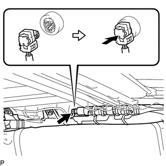
(c) Push in the airbag connector lock to install the airbag connector.
2. INSTALL ROOF HEADLINING ASSEMBLY
Click here .gif)
3. CONNECT CABLE TO NEGATIVE BATTERY TERMINAL
Torque:
5.4 N·m {55 kgf·cm, 48 in·lbf}
NOTICE:
When disconnecting the cable, some systems need to be initialized after the cable is reconnected.
Click here
4. INSPECT SRS WARNING LIGHT
Click here
 Disposal
DISPOSAL
CAUTION / NOTICE / HINT
CAUTION:
Before performing pre-disposal deployment of any SRS part, review and closely
follow all applicable environmental and hazardous material regulations. Pre ...

Other materials:
Seat Belt Buckle Switch LH Circuit Malfunction (B1656/38)
DESCRIPTION
The seat belt buckle switch LH circuit consists of the airbag sensor assembly
and the front seat inner belt assembly LH (seat belt buckle switch LH).
DTC B1655/37 is stored when a malfunction is detected in the seat belt buckle
switch LH circuit.
DTC No.
DTC ...
Stop Light Relay Circuit (C1A4B)
DESCRIPTION
The skid control ECU (master cylinder solenoid)*1 or skid control ECU (brake
actuator assembly)*2 sends a stop light operation request signal to the stop light
relay (stop light switch assembly). If the skid control ECU (master cylinder solenoid)*1
or skid control ECU (brake actua ...
Customize Parameters
CUSTOMIZE PARAMETERS
1. CUSTOMIZE FUNCTION WITH TECHSTREAM
NOTICE:
Be sure to record the current settings before customizing.
These buzzers should be ON for safe driving. Perform these procedure
only if it is necessary to turn the buzzer OFF (disabled).
HINT:
The following ...
