Toyota Tacoma (2015-2018) Service Manual: Components
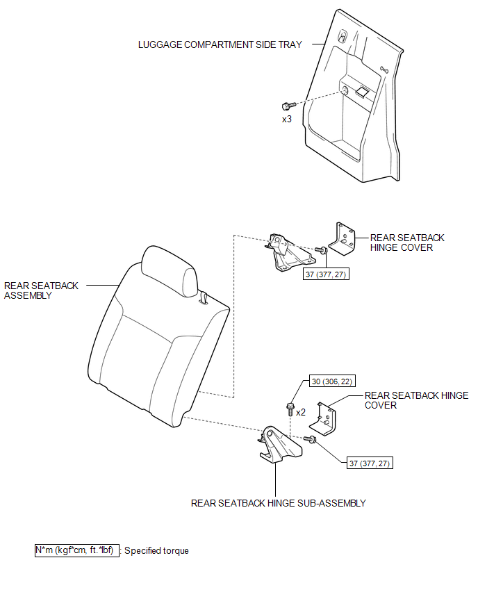
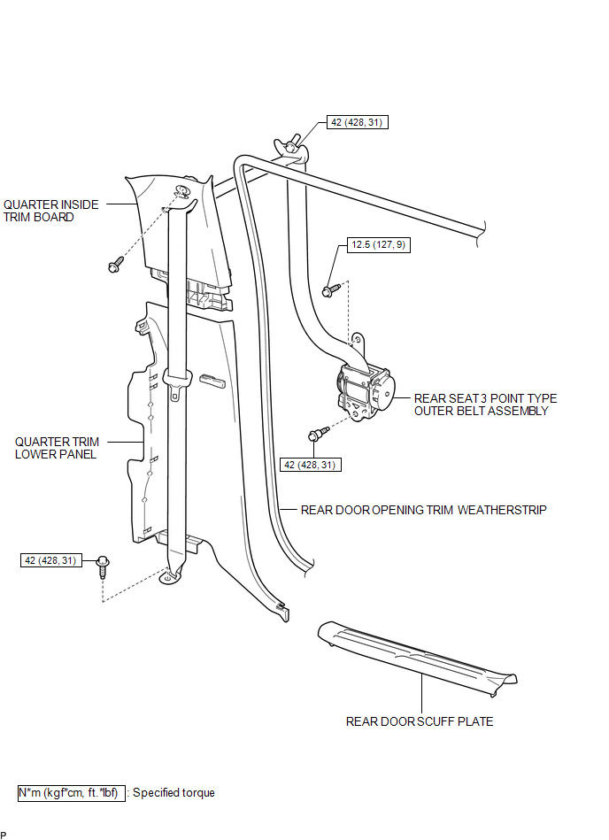
COMPONENTS
ILLUSTRATION
ILLUSTRATION

 Installation
INSTALLATION
PROCEDURE
1. INSTALL REAR SEAT 3 POINT TYPE OUTER BELT ASSEMBLY
(a) Before installing the rear seat 3 point type outer belt assembly,
check the ELR function.
Text in ...
Other materials:
Cellular Phone Registration Failure, Phone Directory Transfer Failure
PROCEDURE
1.
CHECK OPERATION
(a) Place the cellular phone close to the navigation receiver assembly.
(b) Check if the cellular phone can be registered.
OK:
The cellular phone can be registered.
OK
NORMAL OPERATION
...
Removal
REMOVAL
CAUTION / NOTICE / HINT
HINT:
When removing the name plates or stripe tapes, heat the vehicle body or tail
gate and name plates or stripe tapes using a heat light.
Heating Temperature
Item
Temperature
Vehicle Body or Tail Gate
40 to 60 ...
System Diagram
SYSTEM DIAGRAM
...
© 2011-2026 Copyright www.ttguide.net
