Toyota Tacoma (2015-2018) Service Manual: Disassembly
DISASSEMBLY
PROCEDURE
1. REMOVE REAR AXLE SHAFT SNAP RING
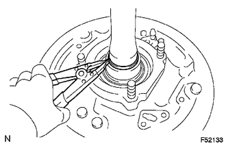
(a) Using a snap ring expander, remove the snap ring.
2. REMOVE REAR AXLE SHAFT
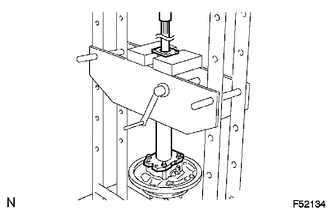
(a) Using SST and press, remove the rear axle shaft.
SST: 09521-25011
SST: 09521-25021
3. REMOVE REAR AXLE BEARING RETAINER INNER
(a) Remove the rear axle bearing retainer inner from the rear axle bearing.
4. REMOVE REAR AXLE SHAFT WASHER
(a) Remove the rear axle shaft washer from the rear axle bearing.
5. REMOVE REAR AXLE HUB AND BEARING ASSEMBLY
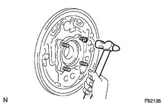
(a) Attach the 4 nuts to the rear axle housing bolts.
(b) Using a hammer, remove the 4 rear axle housing bolts and rear axle bearing.
NOTICE:
Do not reuse the nuts previously removed from the vehicle.
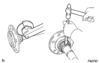
6. REMOVE REAR AXLE HUB BOLT
|
(a) Using SST, remove the 6 hub bolts. SST: 09650-17011 |
|
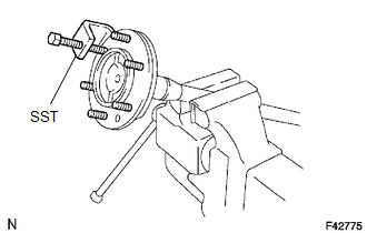
(b) Remove the deflector and deflector gasket from the rear axle shaft.
7. REMOVE REAR AXLE BEARING OIL SEAL
(a) Grind the rear axle bearing inner race surface using a grinder, and then chisel them out with a chisel.
(b) Remove the rear axle shaft oil seal from the rear axle shaft.
 Components
COMPONENTS
ILLUSTRATION
ILLUSTRATION
...
 Inspection
INSPECTION
PROCEDURE
1. INSPECT REAR AXLE SHAFT
(a) Using a dial indicator, measure the runout of the shaft and flange.
Maximum runout:
Shaft runout: 1.5 mm (0.0591 in.)
Flange runout: 0.05 m ...
Other materials:
Traffic Information is not Displayed
CAUTION / NOTICE / HINT
NOTICE:
Traffic information requires payment. An "XM Nav Traffic" contract must
be made between the satellite radio company and the user. If the contract
expires, traffic information will not be available.
Traffic information does not apply to ...
Components
COMPONENTS
ILLUSTRATION
ILLUSTRATION
ILLUSTRATION
ILLUSTRATION
...
Steering Pad Switch
Components
COMPONENTS
ILLUSTRATION
*1
STEERING PAD SWITCH ASSEMBLY
-
-
Removal
REMOVAL
PROCEDURE
1. REMOVE STEERING PAD
(See page )
2. REMOVE STEERING PAD SWITCH ASSEMBLY
(a) Disconnect the 2 connectors.
...
