Toyota Tacoma (2015-2018) Service Manual: Removal
REMOVAL
PROCEDURE
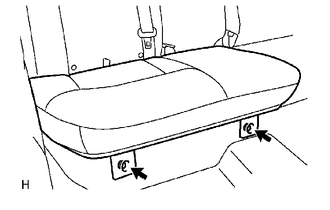
1. REMOVE REAR SEAT CUSHION ASSEMBLY
|
(a) Remove the 2 bolts and rear seat cushion assembly. |
|
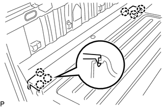
2. REMOVE REAR SEATBACK HINGE COVER
|
(a) Disengage the 6 claws to remove the 2 rear seatback hinge covers. |
|
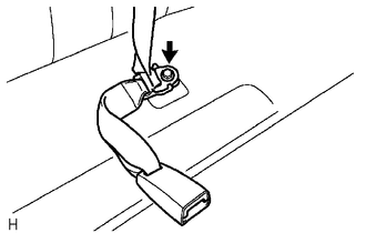
3. REMOVE REAR SEATBACK ASSEMBLY
|
(a) Remove the bolt to disconnect rear seat inner belt assembly and rear center seat outer belt assembly. |
|
|
(b) Remove the 2 bolts and rear seatback assembly. |
|
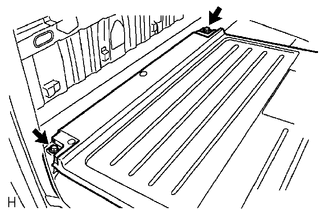
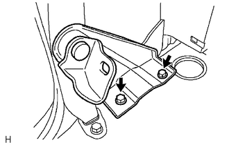
4. REMOVE REAR SEATBACK HINGE SUB-ASSEMBLY
|
(a) Remove the 2 bolts and rear seatback hinge sub-assembly. |
|
 Components
COMPONENTS
ILLUSTRATION
ILLUSTRATION
ILLUSTRATION
...
 Installation
INSTALLATION
PROCEDURE
1. INSTALL REAR SEATBACK HINGE SUB-ASSEMBLY
(a) Install the rear seatback hinge sub-assembly with the 2 bolts.
Torque:
30 N·m {306 kgf·cm, 22 ft·lbf}
2. INSTALL REAR S ...
Other materials:
Lost Communication with ECM/PCM "A" Missing Message (U010087)
DESCRIPTION
The engine control unit and the transmission control unit are located inside
the ECM. The engine control unit intercommunicates with the transmission control
unit with the Controller Area Network (CAN).
If there is a problem in this intercommunication, the ECM stores a DTC.
...
Removal
REMOVAL
PROCEDURE
1. REMOVE SHIFT LEVER KNOB SUB-ASSEMBLY (for Automatic Transmission)
(a) Using a molding remover A, disengage the 2 claws to separate the
shifting hole cover sub-assembly.
(b) Rotate the shift lever knob sub-as ...
Removal
REMOVAL
CAUTION / NOTICE / HINT
HINT:
When removing the name plates or stripe tapes, heat the vehicle body or tail
gate and name plates or stripe tapes using a heat light.
Heating Temperature
Item
Temperature
Vehicle Body or Tail Gate
40 to 60 ...
