Toyota Tacoma (2015-2018) Service Manual: Cargo Light
Components
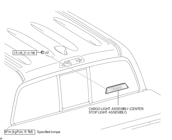
COMPONENTS
ILLUSTRATION
Removal
REMOVAL
PROCEDURE
1. REMOVE ROOF HEADLINING ASSEMBLY
- for Double Cab:
(See page
.gif) )
) - for Access Cab:
(See page
)
2. REMOVE CARGO LIGHT ASSEMBLY (CENTER STOP LIGHT ASSEMBLY)
|
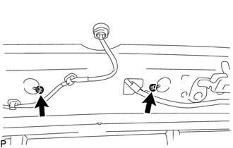
(a) Remove the 2 nuts. |
|
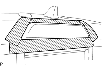
(b) Apply protective tape around the cargo light assembly (center stop light assembly).
 Text in Illustration
.png) |
Protective Tape |
|
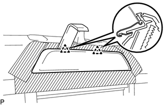
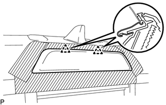
(c) Using a moulding remover D, disengage the 2 clips to separate the cargo light assembly (center stop light assembly). |
|
|
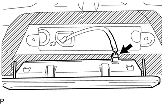
(d) Disconnect the connector to remove the cargo light assembly (center stop light assembly). |
|
Inspection
INSPECTION
PROCEDURE
1. INSPECT CARGO LIGHT ASSEMBLY (CENTER STOP LIGHT ASSEMBLY)
(a) Check the illuminates.
|
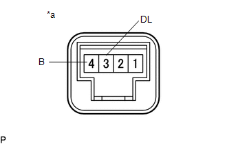
(1) Apply battery voltage to the connector and check the light illumination condition. Text in Illustration
OK:
If the result is not as specified, replace the cargo light assembly (center stop light assembly). |
|
Installation
INSTALLATION
PROCEDURE
1. INSTALL CARGO LIGHT ASSEMBLY (CENTER STOP LIGHT ASSEMBLY)
(a) Connect the connector.
|
(b) Engage the 2 clips to install the cargo light assembly (center stop light assembly). |
|
(c) Install the 2 nuts.
Torque:
3.6 N·m {36 kgf·cm, 31 in·lbf}
(d) Remove the protective tape.
2. INSPECT ROOF HEADLINING ASSEMBLY
- for Double Cab:
(See page
.gif) )
) - for Access Cab:
(See page
)
 Automatic Light Control Sensor
Components
COMPONENTS
ILLUSTRATION
Installation
INSTALLATION
PROCEDURE
1. INSTALL AUTOMATIC LIGHT CONTROL SENSOR
(a) Engage the 2 claws to install the automatic light control sensor.
2. ...
 Cargo Light Switch
Components
COMPONENTS
ILLUSTRATION
Inspection
INSPECTION
PROCEDURE
1. INSPECT DECK LIGHT SWITCH ASSEMBLY
(a) Check the resistance.
(1) Measure the resistance according to the ...
Other materials:
Transmission Fluid Temperature Sensor "B" Circuit Low Input (P2742,P2743)
DESCRIPTION
The No. 2 ATF temperature sensor is installed in the transmission valve body
assembly.
If the ECM detects an abnormally high ATF temperature near this sensor, it illuminates
the warning indicator.
HINT:
The temperature of ATF easily rises when towing, climbing hills, in
...
If you have a flat tire
Remove the flat tire and replace it with the spare provided.
■ Before jacking up the vehicle
● Stop the vehicle on a hard, flat surface.
● Set the parking brake.
● Shift the shift lever to P (automatic transmission) or R (manual transmission).
● Stop the engine.
& ...
Removal
REMOVAL
PROCEDURE
1. REMOVE FRONT DOOR SCUFF PLATE LH (for Double Cab)
2. REMOVE FRONT DOOR SCUFF PLATE LH (for Access Cab)
3. REMOVE COWL SIDE TRIM BOARD LH
4. REMOVE INSTRUMENT CLUSTER CENTER FINISH PANEL SUB-ASSEMBLY
5. REMOVE INSTRUMENT CLUSTER FINISH PANEL ASSEMBLY
6. ...
