Toyota Tacoma (2015-2018) Service Manual: Disassembly
DISASSEMBLY
PROCEDURE
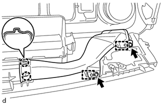
1. REMOVE NO. 1 HEATER TO REGISTER DUCT
|
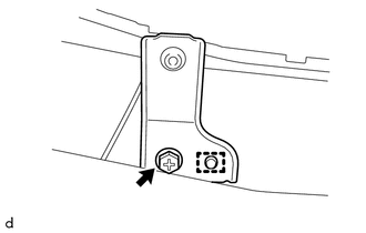
(a) Remove the 2 screws <F> and screw <D>. |
|
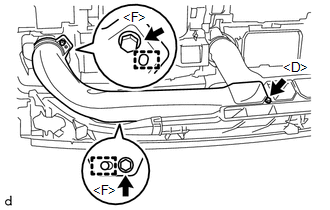
(b) Disengage the 2 guides to remove the No. 1 heater to register duct.
2. REMOVE NO. 3 HEATER TO REGISTER DUCT
|
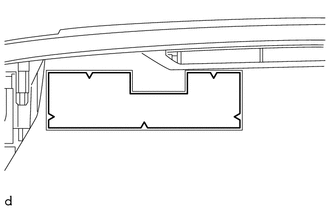
(a) Remove the 2 screws <F> and screw <D>. |
|
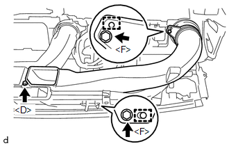
(b) Disengage the 2 guides to remove the No. 3 heater to register duct.
3. REMOVE NO. 2 HEATER TO REGISTER DUCT
|
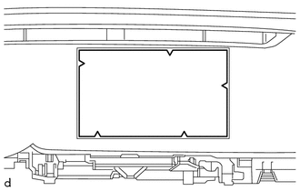
(a) Remove the 2 screws <F> and screw <D>. |
|
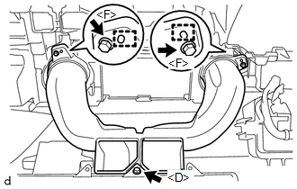
(b) Disengage the 2 guides to remove the No. 2 heater to register duct.
4. REMOVE SIDE NO. 1 DEFROSTER NOZZLE DUCT
|
(a) Remove the 2 screws <F>. |
|
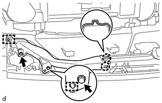
(b) Disengage the 2 guides.
(c) Disengage the 2 claws to remove the side No. 1 defroster nozzle duct.
5. REMOVE SIDE NO. 2 DEFROSTER NOZZLE DUCT
|
(a) Remove the 2 screws <F>. |
|
(b) Disengage the 2 guides.
(c) Disengage the 2 claws to remove the side No. 2 defroster nozzle duct.
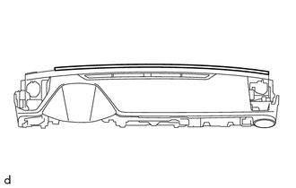
6. REMOVE DEFROSTER NOZZLE ASSEMBLY
|
(a) Remove the 3 screws <F>. |
|
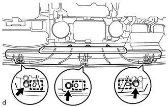
(b) Disengage the 3 guides to remove the defroster nozzle assembly.
7. REMOVE NO. 1 INSTRUMENT PANEL REGISTER SUB-ASSEMBLY
|
(a) Disengage the 6 claws and 3 guides to remove the No. 1 instrument panel register sub-assembly. |
|
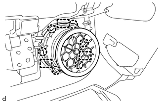
8. REMOVE NETWORK GATEWAY ECU
.gif)
9. REMOVE NAVIGATION ANTENNA ASSEMBLY (w/ Navigation System)
10. REMOVE ANTENNA CORD SUB-ASSEMBLY
11. REMOVE INSTRUMENT PANEL PASSENGER WITHOUT DOOR AIRBAG ASSEMBLY
12. REMOVE NO. 1 INSTRUMENT PANEL PIN
HINT:
Use the same procedure as for the opposite side.
|
(a) Remove the screw <F>. |
|
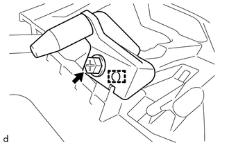
(b) Disengage the guide to remove the No. 1 instrument panel pin.
13. REMOVE NO. 1 METER HOOD RETAINER
HINT:
Use the same procedure as for the opposite side.
|
(a) Remove the screw <D>. |
|
(b) Disengage the guide to remove the No. 1 meter hood retainer.
14. REMOVE NO. 1 INSTRUMENT PANEL CUSHION
|
(a) Remove the No. 1 instrument panel cushion. |
|
15. REMOVE NO. 2 INSTRUMENT PANEL CUSHION
|
(a) Remove the No. 2 instrument panel cushion. |
|
16. REMOVE NO. 4 INSTRUMENT PANEL CUSHION
|
(a) Remove the No. 4 instrument panel cushion. |
|
17. REMOVE INSTRUMENT PANEL CUSHION
|
(a) Remove the instrument panel cushion. |
|
 Components
COMPONENTS
ILLUSTRATION
ILLUSTRATION
ILLUSTRATION
ILLUSTRATION
ILLUSTRATION
ILLUSTRATION
ILLUSTRATION
ILLUSTRATION
...
 Removal
REMOVAL
PROCEDURE
1. TABLE OF BOLT, SCREW AND NUT
HINT:
All bolts, screws and nuts relevant to installing and removing the instrument
panel are shown along with their alphabetic codes in the tab ...
Other materials:
Removal
REMOVAL
PROCEDURE
1. PRECAUTION
NOTICE:
After turning the ignition switch off, waiting time may be required before disconnecting
the cable from the negative (-) battery terminal. Therefore, make sure to read the
disconnecting the cable from the negative (-) battery terminal notices before pr ...
Diagnosis System
DIAGNOSIS SYSTEM
1. DESCRIPTION
(a) Sliding roof system data and Diagnostic Trouble Codes (DTCs) can be read
through the vehicle Data Link Connector 3 (DLC3). When the system seems to be malfunctioning,
use the Techstream to check for malfunctions and perform repairs.
2. CHECK DLC3
(a) Check ...
Components
COMPONENTS
ILLUSTRATION
HINT:
The following specifications are for BD20D (w/o Differential Lock). BD20D differentials
are equipped with M8 rear differential carrier to rear axel housing fasteners.
ILLUSTRATION
ILLUSTRATION
...
