Toyota Tacoma (2015-2018) Service Manual: Inspection
INSPECTION
PROCEDURE
1. INSPECT CAMSHAFT TIMING OIL CONTROL SOLENOID ASSEMBLY
(a) Check the operation.
|
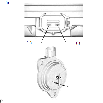
(1) Apply battery voltage between the terminals and check that the plunger operates. Text in Illustration
OK: The plunger extends outwards 5.9 mm (0.232 in.) or more. If the result is not as specified, replace the camshaft timing oil control solenoid assembly. |
|
 On-vehicle Inspection
ON-VEHICLE INSPECTION
PROCEDURE
1. INSPECT CAMSHAFT TIMING OIL CONTROL SOLENOID ASSEMBLY (for Intake Side)
(a) Connect the Techstream to the DLC3.
(b) Start the engine.
(c) Turn the Techstream on ...
 Removal
REMOVAL
PROCEDURE
1. REMOVE FRONT FENDER SEAL RH
HINT:
Use the same procedure as for the LH side (See page
).
2. REMOVE V-BANK COVER SUB-ASSEMBLY
3. REMOVE AIR CLEANER CAP AND HOSE
4. ...
Other materials:
Inspection
INSPECTION
PROCEDURE
1. INSPECT OIL CLEARANCE
(a) Using a micrometer and caliper gauge, measure the oil seal clearance.
Text in Illustration
*1
Pulley Shaft
*2
Front Vane Pump Housing
...
System Description
SYSTEM DESCRIPTION
1. DESCRIPTION
The differential system (w/ Differential Lock) directly connects the
rear left and right wheels so that even if one wheel slips while driving
where drive torque transmission is difficult (such as on sand), the drive
torque of the other wheel is ...
Unusual Bank Angle Detected (C1440)
DESCRIPTION
If the skid control ECU (brake actuator assembly) determines that the vehicle
is being driven at a steep bank angle, the skid control ECU (brake actuator assembly)
stores DTC C1440 while VSC operation is temporarily disabled.
This is not a malfunction if the system and sensor circu ...
