Toyota Tacoma (2015-2018) Service Manual: Removal
REMOVAL
PROCEDURE
1. REMOVE FRONT FENDER SEAL RH
HINT:
Use the same procedure as for the LH side (See page
.gif) ).
).
2. REMOVE V-BANK COVER SUB-ASSEMBLY
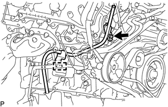
3. REMOVE AIR CLEANER CAP AND HOSE
4. REMOVE ENGINE OIL LEVEL DIPSTICK GUIDE
(a) Remove the engine oil level dipstick.
|
(b) Disengage the clamp to separate the wire harness. |
|
(c) Remove the bolt and engine oil level dipstick guide from the timing chain cover assembly and oil pan sub-assembly.
(d) Remove the O-ring from the engine oil level dipstick guide.
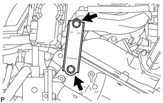
5. REMOVE THROTTLE BODY BRACKET
|
(a) Remove the 2 bolts and throttle body bracket from the intake air surge tank assembly and timing chain cover assembly. |
|
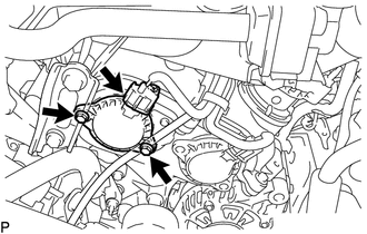
6. REMOVE CAMSHAFT TIMING OIL CONTROL SOLENOID ASSEMBLY (for Intake Side of Bank 1)
|
(a) Disconnect the connector from the camshaft timing oil control solenoid assembly. |
|
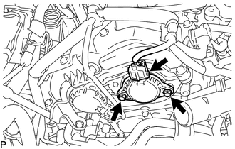
(b) Remove the 2 bolts and camshaft timing oil control solenoid assembly from the timing chain cover assembly.
(c) Remove the O-ring from the camshaft timing oil control solenoid assembly.
HINT:
- Make sure to remove the O-ring completely, as the O-ring may remain on the timing chain cover assembly side.
- Do not drop the O-ring into the timing chain cover assembly.
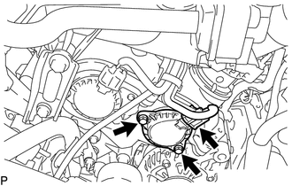
7. REMOVE CAMSHAFT TIMING OIL CONTROL SOLENOID ASSEMBLY (for Exhaust Side of Bank 1)
|
(a) Disconnect the connector from the camshaft timing oil control solenoid assembly. |
|
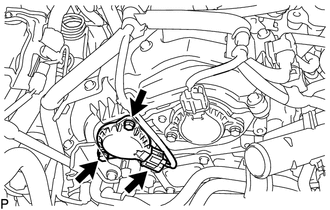
(b) Remove the 2 bolts and camshaft timing oil control solenoid assembly from the timing chain cover assembly.
(c) Remove the O-ring from the camshaft timing oil control solenoid assembly.
HINT:
- Make sure to remove the O-ring completely, as the O-ring may remain on the timing chain cover assembly side.
- Do not drop the O-ring into the timing chain cover assembly.
8. REMOVE CAMSHAFT TIMING OIL CONTROL SOLENOID ASSEMBLY (for Intake Side of Bank 2)
|
(a) Disconnect the connector from the camshaft timing oil control solenoid assembly. |
|
(b) Remove the 2 bolts and camshaft timing oil control solenoid assembly from the timing chain cover assembly.
(c) Remove the O-ring from the camshaft timing oil control solenoid assembly.
HINT:
- Make sure to remove the O-ring completely, as the O-ring may remain on the timing chain cover assembly side.
- Do not drop the O-ring into the timing chain cover assembly.
9. REMOVE CAMSHAFT TIMING OIL CONTROL SOLENOID ASSEMBLY (for Exhaust Side of Bank 2)
|
(a) Disconnect the connector from the camshaft timing oil control solenoid assembly. |
|
(b) Remove the 2 bolts and camshaft timing oil control solenoid assembly from the timing chain cover assembly.
(c) Remove the O-ring from the camshaft timing oil control solenoid assembly.
HINT:
- Make sure to remove the O-ring completely, as the O-ring may remain on the timing chain cover assembly side.
- Do not drop the O-ring into the timing chain cover assembly.
 Inspection
INSPECTION
PROCEDURE
1. INSPECT CAMSHAFT TIMING OIL CONTROL SOLENOID ASSEMBLY
(a) Check the operation.
(1) Apply battery voltage between the terminals and check that the plunger
ope ...
 Installation
INSTALLATION
PROCEDURE
1. INSTALL CAMSHAFT TIMING OIL CONTROL SOLENOID ASSEMBLY (for Intake Side of
Bank 1)
(a) Apply engine oil to a new O-ring and install it to the camshaft timing
...
Other materials:
Neutral Position Switch
Components
COMPONENTS
ILLUSTRATION
*1
NEUTRAL POSITION SWITCH
*2
GASKET
N*m (kgf*cm, ft.*lbf): Specified torque
â—Ź
Non-reusable part
Installation
INSTALLATION
PROCEDURE
1. INSTALL NEUTR ...
Installation
INSTALLATION
CAUTION / NOTICE / HINT
HINT:
Use the same procedure for both the RH and LH sides.
The procedure described below is for the LH side.
PROCEDURE
1. INSTALL CURTAIN SHIELD AIRBAG ASSEMBLY
(a) Insert the 5 hooks, install 6 new bolts, 2 new clips with pins and 2 new
...
Disassembly
DISASSEMBLY
CAUTION / NOTICE / HINT
CAUTION:
Wear protective gloves. Sharp areas on the parts may injure your hands.
PROCEDURE
1. REMOVE REAR SEAT CUSHION BAND
(a) Remove the screw and rear seat cushion band.
2. REMOVE REAR SEAT HEADREST HO ...
