Toyota Tacoma (2005–2015) Owners Manual: Indicators and warning lights
The indicator and warning lights on the instrument cluster and center panel inform the driver of the status of the vehicle’s various systems.
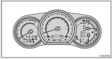
 Instrument cluster
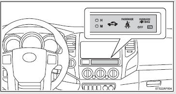
 Center panel
■ Indicators
The indicators inform the driver of the operating state of the vehicle’s various systems.
 Turn signal indicator
 Headlight high beam indicator
 Headlight indicator
 Tail light indicator
 Security indicator
 Shift position and shift range indicators
 Shift position and shift range indicators
 Cruise control indicator
 Slip indicator
 VSC OFF indicator
 TRAC OFF indicator
 Downhill assist control system indicator
 RSCA OFF indicator
 Active traction control system
indicator
Active traction control system
indicator
 AUTO LSD indicator
 Four-wheel drive indicator
 4LO indicator
 Rear differential lock indicator
 AIR BAG ON indicator
 AIR BAG OFF indicator
■ Warning lights
Warning lights inform the driver of malfunctions in any of the vehicle’s systems.
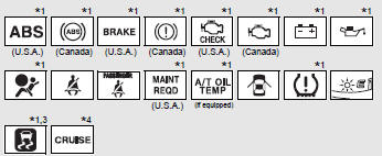
*1: These lights turn on when the engine switch is turned to the ON position to indicate that a system check is being performed. They will turn off after the engine is started, or after a few seconds. There may be a malfunction in a system if a light does not come on, or if the lights do not turn off. Have the vehicle inspected by your Toyota dealer.
*2: The indicator flashes to indicate that the system is operating.
*3: The indicator light comes on to indicate a malfunction.
*4: The indicator flashes to indicate a malfunction.
*5: For 2WD models, even though there is no function of deactivating the curtain shield airbags in a vehicle rollover, the RSCA OFF indicator turns on briefly when the engine switch is turned to the ON position. But this is not a malfunction.
CAUTION
■If a safety system warning light does not come on
Should a safety system light such as ABS and the SRS airbag warning light not come on when you start the engine, this could mean that these systems are not available to help protect you in an accident, which could result in death or serious injury. Have the vehicle inspected by your Toyota dealer immediately if this occurs.
 Gauges and meters
The following gauges, meters and displays illuminate when the engine switch is
in the ON position.
Tachometer
Displays the engine speed in revolutions per minute.
Speedometer
Displays the vehi ...

Other materials:
Operation Check
OPERATION CHECK
1. CHECK WINDOW LOCK FUNCTION
(a) Turn the ignition switch ON.
(b) Press the window lock switch of the power window regulator master switch
assembly.
HINT:
The illumination (LED) built into the switch knob of each seat does not turn
off.
(c) Check that the power window fo ...
Head restraints
Head restraints are provided for all seats.
■ Adjusting the head restraints
Bench type front seat
Up
Pull the head restraints up.
Down
Push the head restraint down while pushing the lock release button.
Separated type front seat
Up
Pull the head restraints up.
Down
Push th ...
Tire information
Typical tire symbols
1. Tire size
2. DOT and Tire Identification Number (TIN)
3. Location of treadwear indicators
4. Tire ply composition and materials
Plies are layers of rubber-coated parallel cords. Cords are the strands which
form the plies in a tire.
5. Uniform tire quality grading
F ...
