Toyota Tacoma (2015-2018) Service Manual: Inspection
INSPECTION
PROCEDURE
1. INSPECT OUTER MIRROR LH
|
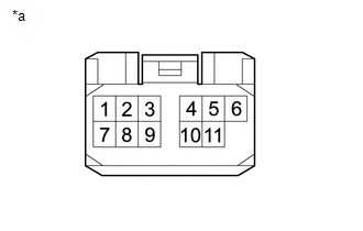
(a) Check the outer mirror heater operation. Text in Illustration
(1) Measure the resistance according to the value(s) in the table below. Standard Resistance:
If the result is not as specified, replace the outer mirror LH. |
|
|
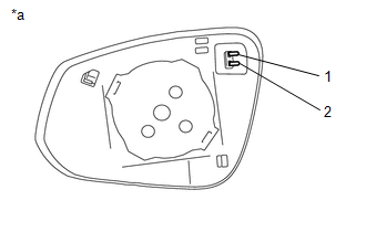
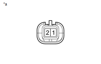
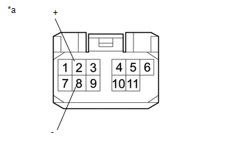
(b) Check the operation of the outer rear view mirror indicator. (w/ Blind Spot Monitor) Text in Illustration
(1) Apply 6 V battery voltage to the terminals of the connector, and check that the outer rear view mirror indicator comes on. NOTICE: Do not apply a voltage of more than 6 V. HINT: Connect 4 new 1.5 V dry-cell batteries in series. OK:
If the result is not as specified, replace the outer mirror LH. |
|
2. INSPECT OUTER MIRROR RH
|
(a) Check the outer mirror heater operation. Text in Illustration
(1) Measure the resistance according to the value(s) in the table below. Standard Resistance:
If the result is not as specified, replace the outer mirror RH. |
|
|
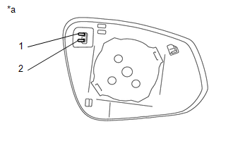
(b) Check the operation of the outer rear view mirror indicator. (w/ Blind Spot Monitor) Text in Illustration
(1) Apply 6 V battery voltage to the terminals of the connector, and check that the outer rear view mirror indicator comes on. NOTICE: Do not apply a voltage of more than 6 V. HINT: Connect 4 new 1.5 V dry-cell batteries in series. OK:
If the result is not as specified, replace the outer mirror RH. |
|
3. INSPECT OUTER REAR VIEW MIRROR ASSEMBLY LH
|
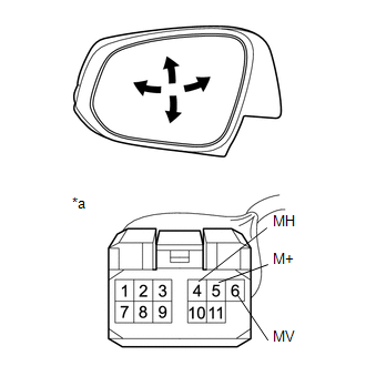
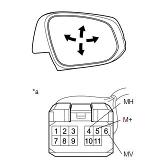
(a) Check the operation of the mirror surface. Text in Illustration
(1) Apply battery voltage and check the operation of the mirror. OK:
If the result is not as specified, replace the outer rear view mirror assembly LH. |
|
|
(b) Check the side turn signal light assembly LH. Text in Illustration
(1) Apply battery voltage to the terminals of the connector, and check the illumination condition. OK:
If the result is not as specified, replace the outer rear view mirror assembly LH. |
|
|
(c) Check the operation of the mirror heater. Text in Illustration
(1) Measure the resistance according to the value(s) in the table below. Standard Resistance:
If the result is not as specified, replace the outer rear view mirror assembly LH. (2) Connect the cable from the positive (+) battery terminal to terminal 2 (+) and the negative (-) battery terminal to terminal 8 (-), and then check that the mirror becomes warm. HINT: It takes a short time for the mirror to become warm. OK: Mirror becomes warm. If the result is not as specified, replace the outer rear view mirror assembly LH. |
|
|
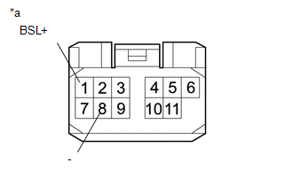
(d) Check the operation of the BSM. Text in Illustration
(1) Apply 6 V dry-cell battery voltage to the terminals of the connector, and check the illumination condition. NOTICE: Do not apply a voltage of 6 V or higher. HINT: Connect the 1.5 V 4 pieces batteries of a new series, applying a 6 V voltage of between each terminal of the connector. OK:
If the result is not as specified, replace the outer rear view mirror assembly LH. |
|
4. INSPECT OUTER REAR VIEW MIRROR ASSEMBLY RH
|
(a) Check the operation of the mirror surface. Text in Illustration
(1) Apply battery voltage and check the operation of the mirror. OK:
If the result is not as specified, replace the outer rear view mirror assembly RH. |
|
|
(b) Check the side turn signal light assembly RH. Text in Illustration
(1) Apply battery voltage to the terminals of the connector, and check the illumination condition. OK:
If the result is not as specified, replace the outer rear view mirror assembly RH. |
|
|
(c) Check the operation of the mirror heater. Text in Illustration
(1) Measure the resistance according to the value(s) in the table below. Standard Resistance:
If the result is not as specified, replace the outer rear view mirror assembly RH. (2) Connect the cable from the positive (+) battery terminal to terminal 2 (+) and the negative (-) battery terminal to terminal 8 (-), and then check that the mirror becomes warm. HINT: It takes a short time for the mirror to become warm. OK: Mirror becomes warm. If the result is not as specified, replace the outer rear view mirror assembly RH. |
|
|
(d) Check the operation of the BSM. Text in Illustration
(1) Apply 6 V dry-cell battery voltage to the terminals of the connector, and check the illumination condition. NOTICE: Do not apply a voltage of 6 V or higher. HINT: Connect the 1.5 V 4 pieces batteries of a new series, applying a 6 V voltage of between each terminal of the connector. OK:
If the result is not as specified, replace the outer rear view mirror assembly RH. |
|
 Disassembly
DISASSEMBLY
CAUTION / NOTICE / HINT
HINT:
Use the same procedures for both the LH and RH sides.
The procedure described below is for the LH side.
PROCEDURE
1. REMOVE OUTER MIRRO ...
 Reassembly
REASSEMBLY
CAUTION / NOTICE / HINT
HINT:
Use the same procedures for both the LH and RH sides.
The procedure described below is for the LH side.
PROCEDURE
1. INSTALL SIDE TURN S ...
Other materials:
Four Wheel Drive (4WD) Low Switch Circuit Range / Performance (P2772)
DESCRIPTION
This DTC is output when a malfunction in the L4 detection switch is detected.
DTC No.
Detection Item
DTC Detection Condition
Trouble Area
P2772
Four Wheel Drive (4WD) Low Switch Circuit Range / Performance
...
Parts Location
PARTS LOCATION
ILLUSTRATION
*A
for Vacuum Brake Booster
*B
for Hydraulic Brake Booster
*1
BRAKE ACTUATOR ASSEMBLY (SKID CONTROL ECU)
*2
BRAKE BOOSTER WITH MASTER CYLINDER ASSEMBLY (SKID CONTROL ECU)
...
Connecting BluetoothÂź
The following can be performed using BluetoothÂź wireless communication: ■
A portable audio player can be operated and listened to via multimedia system
■ Hands-free phone calls can be made via a cellular phone
In order to use wireless communication, register and connect a Bluetooth ...
