Toyota Tacoma (2015-2018) Service Manual: Components
COMPONENTS
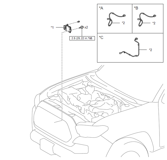
ILLUSTRATION
|
*A |
for Type A |
*B |
for Type B |
|
*C |
for Type C |
- |
- |
|
*1 |
MILLIMETER WAVE RADAR SENSOR ASSEMBLY |
*2 |
MILLIMETER WAVE RADAR WIRE |
.png) |
N*m (kgf*cm, ft.*lbf): Specified torque |
- |
- |

 Adjustment
ADJUSTMENT
CAUTION / NOTICE / HINT
CAUTION:
Radiofrequency radiation exposure information:
This equipment complies with FCC radiation exposure limits set forth
for an uncontrolled envir ...
Other materials:
Main Switch Illumination Circuit
DESCRIPTION
When the light control switch is turned to the tail or head position, this circuit
sends an illumination signal to the wireless charger main switch (mobile wireless
charger switch). Based on this signal, the wireless charger main switch (mobile
wireless charger switch) is illumina ...
Event data recorder
This vehicle is equipped with an event data recorder (EDR). The main purpose
of an EDR is to record, in certain crash or near crash-like situations, such as
an air bag deployment or hitting a road obstacle, data that will assist in understanding
how a vehicle’s systems performed. The EDR is ...
Clutch Switch Circuit
DESCRIPTION
Clutch switch circuit inspection is necessary for manual transmission vehicles.
When the clutch pedal is released, the ECM receives the positive (+) battery
voltage through the ECU-IG NO. 2 fuse and ignition switch. While the clutch pedal
is depressed, the clutch switch assembly se ...
