Toyota Tacoma (2015-2018) Service Manual: Security Indicator Light Does not Blink
DESCRIPTION
- The certification ECU (smart key ECU assembly) blinks the security indicator light when the immobiliser is set (engine switch off, or driver door is opened and closed with engine switch on (IG)).
- The certification ECU (smart key ECU assembly) receive the security indicator light signal from the main body ECU (multiplex network body ECU) via CAN communication when the theft deterrent system is arming preparation state or alarm sounding state. Then, certification ECU (smart key ECU assembly) blinks the security indicator light.
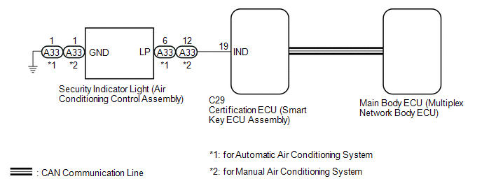
WIRING DIAGRAM
CAUTION / NOTICE / HINT
NOTICE:
- Before replacing the certification ECU (smart key ECU assembly), refer
to the Registration (See page
.gif) ).
). - The engine immobiliser system (w/ Smart Key System) uses the CAN communication
system. Inspect the communication function by following How to Proceed with
Troubleshooting (See page ). Troubleshoot
the engine immobiliser system (w/ Smart Key System) after confirming that
the communication systems are functioning properly.
PROCEDURE
|
1. |
PERFORM ACTIVE TEST USING TECHSTREAM (SECURITY INDICATOR LIGHT) |
(a) Connect the Techstream to the DLC3.
(b) Turn the engine switch on (IG).
(c) Turn the Techstream on.
(d) Enter the following menus: Body Electrical / Smart Key / Active Test.
(e) Perform the Active Test according to the display on the Techstream.
Smart Key|
Tester Display |
Test Part |
Control Range |
Diagnostic Note |
|---|---|---|---|
|
Immobiliser Indicator |
Security indicator light |
OFF/ON |
- |
OK:
The security indicator light operates normally.
| NG | .gif) |
GO TO STEP 3 |
|
.gif)
|
2. |
CHECK SECURITY INDICATOR LIGHT OPERATION |
(a) When the immobiliser is set, check that the security indicator light blinks.*1
OK:
The security indicator light blinks normally.
(b) When the theft deterrent system is in the arming preparation state, check
that the security indicator light on (See page
).*2
OK:
The security indicator light is on normally.
Result|
Result |
Proceed to |
|---|---|
|
*1 is NG (*2 is OK) |
A |
|
*2 is NG (*1 is OK) |
B |
| A | |
REPLACE CERTIFICATION ECU (SMART KEY ECU ASSEMBLY) |
| B | |
REPLACE MAIN BODY ECU (MULTIPLEX NETWORK BODY ECU) |
|
3. |
CHECK HARNESS AND CONNECTOR (SECURITY INDICATOR LIGHT (AIR CONDITIONING CONTROL ASSEMBLY) - CERTIFICATION ECU (SMART KEY ECU ASSEMBLY)) |
(a) Disconnect the A33 security indicator light (air conditioning control assembly) connector.
(b) Disconnect the C29 certification ECU (smart key ECU assembly) connector.
(c) Measure the resistance according to the value(s) in the table below.
Standard Resistance:
|
Tester Connection |
Condition |
Specified Condition |
|---|---|---|
|
A33-6 (LP) - C29-19 (IND)*1 |
Always |
Below 1 Ω |
|
A33-6 (LP) or C29-19 (IND) - Body ground*1 |
Always |
10 kΩ or higher |
|
A33-1 (GND) - Body ground*1 |
Always |
Below 1 Ω |
|
A33-12 (LP) - C29-19 (IND)*2 |
Always |
Below 1 Ω |
|
A33-12 (LP) or C29-19 (IND) - Body ground*2 |
Always |
10 kΩ or higher |
- *1: for Automatic Air Conditioning System
- *2: for Manual Air Conditioning System
| NG | |
REPAIR OR REPLACE HARNESS OR CONNECTOR |
|
|
4. |
CHECK CERTIFICATION ECU (SMART KEY ECU ASSEMBLY) |
(a) Reconnect the C29 certification ECU (smart key ECU assembly) connector.
(b) Measure the voltage and check the pulse according to the value(s) in the table below.
Standard Voltage:
|
Tester Connection |
Condition |
Specified Condition |
|---|---|---|
|
A33-6 (LP) - A33-1 (GND)*1 |
Engine switch off → engine switch on (IG) |
Pulse generation → Below 2 V |
|
A33-12 (LP) - A33-1 (GND)*2 |
Engine switch off → engine switch on (IG) |
Pulse generation → Below 2 V |
- *1: for Automatic Air Conditioning System
- *2: for Manual Air Conditioning System
|
Result |
Proceed to |
|---|---|
|
OK (for Automatic Air Conditioning System) |
A |
|
OK (for Manual Air Conditioning System) |
B |
|
NG |
C |
| A | |
REPLACE SECURITY INDICATOR LIGHT (AIR CONDITIONING CONTROL ASSEMBLY) |
| B | |
REPLACE SECURITY INDICATOR LIGHT (AIR CONDITIONING CONTROL ASSEMBLY) |
| C | |
REPLACE CERTIFICATION ECU (SMART KEY ECU ASSEMBLY) |
 Short to GND in Immobiliser System Power Source Circuit (B278A)
DESCRIPTION
When there is a short to GND in the power supply for the transponder key amplifier
of the engine switch, the certification ECU (smart key ECU assembly) stores this
DTC.
DT ...
 Immobiliser System does not Operate Properly
DESCRIPTION
The engine immobiliser system compares the ID code that is registered in the
certification ECU (smart key ECU assembly) with the ID code of the transponder chip
that is embedded in th ...
Other materials:
AUTO LSD Indicator Light does not Come ON
DESCRIPTION
The AUTO LSD does not operate even if the VSC OFF switch is pressed under the
following conditions:
The brake system is faulty.
The temperature inside the hydraulic brake booster increases and the
AUTO LSD operation is suspended.
WIRING DIAGRAM
CAUTION / NOTI ...
Cleaning and protecting the vehicle exterior
Perform the following to protect the vehicle and maintain it in prime condition.
● Working from top to bottom, liberally apply water to the vehicle body, wheel
wells and underside of the vehicle to remove any dirt and dust.
Wash the vehicle body using a sponge or soft cloth, such as a cham ...
Lock Switch Circuit
WIRING DIAGRAM
PROCEDURE
1.
CHECK REAR DIFFERENTIAL LOCK INDICATOR LIGHT
(a) Turn the ignition switch to ON.
(b) for 4WD:
Finish switching to L4.
(c) Check the rear differential lock indicator light.
(d) Press the differential lock switch.
(e) After 60 secon ...
