Toyota Tacoma (2015-2018) Service Manual: Removal
REMOVAL
PROCEDURE
1. REMOVE FRONT DOOR SCUFF PLATE LH (for Double Cab)
.gif)
2. REMOVE FRONT DOOR SCUFF PLATE LH (for Access Cab)
3. REMOVE COWL SIDE TRIM BOARD LH
4. REMOVE CENTER INSTRUMENT CLUSTER CENTER FINISH PANEL SUB-ASSEMBLY
5. REMOVE INSTRUMENT CLUSTER FINISH PANEL ASSEMBLY
6. REMOVE INSTRUMENT PANEL LOWER FINISH PANEL SUB-ASSEMBLY RH
7. REMOVE COOLER (ROOM TEMPERATURE SENSOR) THERMISTOR
(a) Disengage the 2claws to disconnect the cooler (room temperature sensor) thermistor.
|
(b) Disconnect the connector. |
|
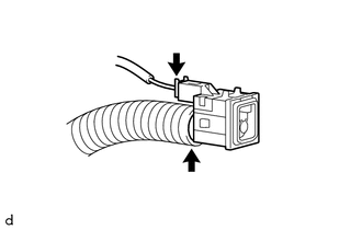
(c) Disconnect the cooler air hose to remove the cooler (room temperature sensor) thermistor.
 Inspection
INSPECTION
PROCEDURE
1. INSPECT COOLER (ROOM TEMPERATURE. SENSOR) THERMISTOR
(a) Check the resistance.
(1) Measure the resistance according to the value(s) in the table below.
Text i ...
 Installation
INSTALLATION
PROCEDURE
1. INSTALL COOLER (ROOM TEMPERATURE SENSOR) THERMISTOR
(a) Connect the cooler air hose.
(b) Connect the connector.
(c) Engage the 2 claws to connect the cooler (room temper ...
Other materials:
Automatic High Beam System does not Operate or Operation Indicator does not
Illuminate
DESCRIPTION
The main body ECU (multiplex network body ECU) controls the automatic high beam
system based on signals received from the forward recognition camera.
WIRING DIAGRAM
CAUTION / NOTICE / HINT
NOTICE:
When replacing the combination meter assembly, always replace it with
...
System Description
SYSTEM DESCRIPTION
1. POWER WINDOW CONTROL SYSTEM DESCRIPTION
(a) The power window control system controls the power window operation using
the power window regulator motors. The main controls of this system are the power
window regulator master switch assembly (mounted on the driver door), po ...
Vehicle Speed Sensor (C1A45)
DESCRIPTION
The blind spot monitor sensor receives vehicle speed signals from the skid control
ECU (brake actuator assembly) via CAN communication.
DTC Code
DTC Detection Condition
Trouble Area
C1A45
A fail flag is transmitted from the ...
