Toyota Tacoma (2015-2018) Service Manual: Reassembly
REASSEMBLY
PROCEDURE
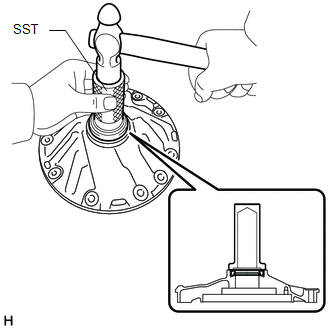
1. INSTALL FRONT OIL PUMP OIL SEAL
|
(a) Using SST and a hammer, install a new front oil pump oil seal to the front oil pump body sub-assembly. SST: 09350-30020 09351-32140 Standard depth: -0.3 to 0.3 mm (-0.0118 to 0.0118 in.) |
|
(b) Coat the lip of the front oil pump oil seal with MP grease.
2. SECURE FRONT OIL PUMP BODY SUB-ASSEMBLY
(a) Place the front oil pump body sub-assembly on the torque converter assembly.
3. INSTALL FRONT OIL PUMP DRIVEN GEAR
|
(a) Coat the front oil pump driven gear with ATF and install it to the front oil pump body sub-assembly. |
|
.png)
4. INSTALL FRONT OIL PUMP DRIVE GEAR
|
(a) Coat the front oil pump drive gear with ATF and install it to the front oil pump body sub-assembly. |
|
.png)
5. INSTALL STATOR SHAFT ASSEMBLY
|
(a) Align the bolt holes of the stator shaft assembly with the bolt holes of the front oil pump body sub-assembly and install the stator shaft assembly to the front oil pump body sub-assembly. |
|
.png)
(b) Using a T30 "TORX" socket wrench, install the 7 screws.
Torque:
11 N·m {110 kgf·cm, 8 ft·lbf}
6. INSTALL FRONT OIL PUMP PLATE
|
(a) Using a T30 "TORX" socket wrench, install the front oil pump plate with the 3 screws. Torque: 11 N·m {110 kgf·cm, 8 ft·lbf} |
|
.png)
7. INSPECT OIL PUMP DRIVE GEAR ROTATION
.gif)
8. INSTALL CLUTCH DRUM OIL SEAL RING
|
(a) Coat 2 new clutch drum oil seal rings with ATF and install them to the oil pump assembly NOTICE:
|
|
.png)
9. INSTALL FRONT OIL PUMP BODY O-RING
|
(a) Coat a new front oil pump body O-ring with ATF and install it to the oil pump assembly. |
|
.png)
 Inspection
INSPECTION
PROCEDURE
1. INSPECT FRONT OIL PUMP BODY SUB-ASSEMBLY
(a) Using a dial indicator, measure the inside diameter of the front
oil pump body sub-assembly bushing.
Maximum i ...

Other materials:
Freeze Frame Data
FREEZE FRAME DATA
1. DESCRIPTION
The ECM records vehicle and driving condition information as freeze frame data
the moment a DTC is stored. When troubleshooting, freeze frame data can be helpful
in determining whether the vehicle was moving or stationary, whether the engine
was warmed up or ...
System Diagram
SYSTEM DIAGRAM
Communication Table
Sender
Receiver
Signal
Communication Method
Power window regulator master switch assembly*1
Main Body ECU (Multiplex Network Body ECU)
Door control switch signal
...
Using the radio
Select “AM” or “FM” on the “Select Audio Source” screen to begin listening
to the radio.
Audio control screen
“Select Audio Source” screen
appears
Preset stations
Select to display RBDS text
message
Scanning for receivable station
Sele ...
