Toyota Tacoma (2005–2015) Owners Manual: Gauges and meters
The following gauges, meters and displays illuminate when the engine switch is in the ON position.
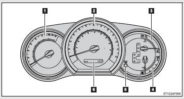
 Tachometer
Displays the engine speed in revolutions per minute.
 Speedometer
Displays the vehicle speed.
 Engine coolant temperature gauge
Displays the engine coolant temperature.
 Fuel gauge
Displays the quantity of fuel remaining in the tank.
 ODO/TRIP button
Switches between odometer and trip meter displays. Pushing and holding the button will reset the trip meter when the trip meter is being displayed.
 Odometer/trip meter
Odometer: Displays the total distance the vehicle has been driven.
Trip meter: Displays the distance the vehicle has been driven since the meter was last reset. Trip meters A and B can be used to record and display different distances independently.
Odometer and trip meter display button
Pressing this button switches between odometer and trip meter displays.
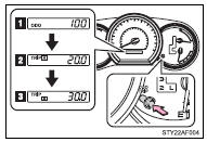
 Odometer
 Trip meter A*
 Trip meter B*
*: Pushing and holding the button will reset the trip meter.
Instrument panel light control
The brightness of the instrument panel lights can be adjusted.
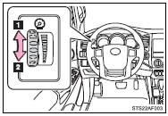
 Brighter
 Darker
NOTICE
■To prevent damage to the engine and its components
●Do not let the indicator needle of the tachometer enter the red zone, which indicates the maximum engine speed.
●The engine may be overheating if the engine coolant temperature gauge is in the red zone (H). In this case, immediately stop the vehicle in a safe place, and check the engine after it has cooled completely.

 Indicators and warning lights
The indicator and warning lights on the instrument cluster and center panel
inform the driver of the status of the vehicle’s various systems.
Instrument cluster
Center panel
■ Indic ...
Other materials:
Dtc Check / Clear
DTC CHECK / CLEAR
NOTICE:
When the diagnosis system is changed from normal mode to check mode or vice versa,
all DTCs and freeze frame data recorded in normal mode are cleared. Before changing
modes, always check and make a note of DTCs and freeze frame data.
HINT:
DTCs which are sto ...
Installation
INSTALLATION
PROCEDURE
1. INSTALL REAR BUMPER ASSEMBLY
(a) Using an engine lifter or equivalent, engage the 2 pins to install the rear
bumper assembly.
Text in Illustration
*a
Pin
-
-
NOTICE:
Using plate lift attachments or equiv ...
VSC Buzzer Circuit
DESCRIPTION
The skid control ECU (master cylinder solenoid) is connected to the combination
meter via CAN communication.
The combination meter has a built-in VSC warning buzzer:
Sounds intermittently to inform the driver if the temperature of hydraulic
brake booster has increased exc ...
