Toyota Tacoma (2015-2018) Service Manual: Fuel Sender Gauge Assembly
Components
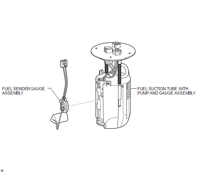
COMPONENTS
ILLUSTRATION
Inspection
INSPECTION
PROCEDURE
1. INSPECT FUEL SENDER GAUGE ASSEMBLY
|
(a) Check that the float moves smoothly between F and E. Text in Illustration
|
|
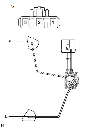
(b) Measure the resistance according to the value(s) in the table below.
Standard Resistance:
|
Tester Connection |
Condition |
Specified Condition |
|---|---|---|
|
2 - 3 |
Float position is F (upper) |
13.5 to 16.5 Ω |
|
Float position is E (lower) |
405.5 to 414.5 Ω |
If the result is not as specified, replace the fuel sender gauge assembly.
Removal
REMOVAL
PROCEDURE
1. REMOVE FUEL SUCTION TUBE WITH PUMP AND GAUGE ASSEMBLY
(See page .gif) )
)
2. REMOVE FUEL SENDER GAUGE ASSEMBLY
|
(a) Disconnect the fuel sender gauge assembly connector. |
|
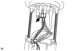
(b) Disengage the clamp and disconnect the wire harness.
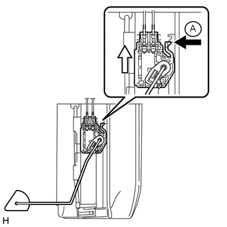
(c) Press down on the fuel sender gauge claw labeled A. Then slide the fuel sender gauge assembly upward to remove it.
 Text in Illustration
.png) |
Press down |
.png) |
Slide |
Installation
INSTALLATION
PROCEDURE
1. INSTALL FUEL SENDER GAUGE ASSEMBLY
(a) Set the fuel sender gauge assembly on the No. 1 fuel sub-tank. Then slide the fuel sender gauge assembly downward to install it.
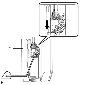 Text in Illustration
|
*1 |
No. 1 Fuel Sub-Tank |
.png) |
Slide |
(b) Engage the clamp and connect the wire harness.
(c) Connect the fuel sender gauge assembly connector.
2. INSTALL FUEL SUCTION TUBE WITH PUMP AND GAUGE ASSEMBLY
(See page .gif) )
)
 Installation
INSTALLATION
CAUTION / NOTICE / HINT
HINT:
Perform "Inspection After Repairs" after replacing the fuel pump assembly (See
page ).
PROCEDURE
1. SET FUEL PUMP ASSEMBLY
HINT:
Perform ...
 Fuel System
...
Other materials:
Brake
General Maintenance
GENERAL MAINTENANCE
PROCEDURE
1. INSPECT BRAKE LINE PIPES AND HOSES
HINT:
Work in a well-lighted area. Turn the front wheels fully to the right or left
before beginning.
(a) Check all the brake lines and hoses for:
Damage
Wear
Deformation
Cracks
...
Driver Side Power Window does not Operate with Power Window Master Switch
DESCRIPTION
When the engine is running or the ignition switch is ON, the front power window
regulator motor assembly LH is operated by the power window regulator master switch
assembly. The front power window regulator motor assembly LH has motor, regulator,
and ECU functions.
HINT:
If the ...
How To Proceed With Troubleshooting
CAUTION / NOTICE / HINT
HINT:
Perform the following procedure to troubleshoot the dynamic radar cruise
control system.
*: Use the Techstream.
PROCEDURE
1.
VEHICLE BROUGHT TO WORKSHOP
NEXT
...
