Toyota Tacoma (2015-2018) Service Manual: Reassembly
REASSEMBLY
PROCEDURE
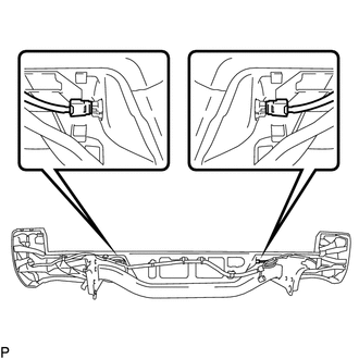
1. INSTALL REAR BUMPER SIDE STAY LH
|
(a) Install the rear bumper side stay LH with the 2 bolts. Torque: 30 N·m {306 kgf·cm, 22 ft·lbf} |
|
.png)
2. INSTALL REAR BUMPER SIDE STAY RH
HINT:
Use the same procedure as for the LH side.
3. INSTALL NO. 6 FLOOR WIRE
|
(a) Engage the wire harness clamps to install the No. 6 floor wire. Text in Illustration
|
|
.png)
(b) Install 2 new adhesive tapes.
4. INSTALL BLIND SPOT MONITOR SENSOR LH (w/ Blind Spot Monitor)
|
(a) Install the blind spot monitor sensor LH with the 3 nuts. Torque: 9.0 N·m {92 kgf·cm, 80 in·lbf} |
|
.png)
(b) Connect the connector.
5. INSTALL BLIND SPOT MONITOR SENSOR RH (w/ Blind Spot Monitor)
HINT:
Use the same procedure as for the LH side.
6. INSTALL NO. 1 ULTRASONIC SENSOR (w/ Clearance Sonar System)
.gif)
7. INSTALL REAR BUMPER EXTENSION LH
(a) w/ Clearance Sonar System:
|
(1) Connect the connector. Text in Illustration
|
|
.png)
(b) Install the rear bumper extension LH.
(c) Install the clamp.
(d) Install the 5 clips.
8. INSTALL REAR BUMPER EXTENSION RH
HINT:
Use the same procedure as for the LH side.
9. INSTALL REAR BUMPER PLATE
(a) Engage the 6 guides to install the rear bumper plate.
.png) Text in Illustration
Text in Illustration
|
*a |
Wire Harness Clamp |
*b |
Guide |
(b) Install the 10 bolts.
Torque:
30 N·m {306 kgf·cm, 22 ft·lbf}
(c) Engage the wire harness clamps.
10. INSTALL NO. 1 ULTRASONIC SENSOR (w/ Clearance Sonar System)
11. INSTALL REAR BUMPER PAD SUB-ASSEMBLY
|
(a) Engage the 2 claws to install the license plate light lens. HINT: Use the same procedure for the RH side and LH side. |
|
.png)
(b) w/ Clearance Sonar System:
(1) Connect the 2 connectors.
.png)
(2) Engage the 14 claws to install the rear bumper pad sub-assembly.
(3) Install the 3 clips.
(c) w/o Clearance Sonar System:
(1) Engage the 14 claws to install the rear bumper pad sub-assembly.
.png)
(2) Install the 3 clips.
|
(d) Connect the connector to install the license plate light. HINT: Use the same procedure for the RH side and LH side. |
|
.png)
|
(e) Install the 2 license plate light assemblies. |
|
12. INSTALL REAR BUMPER HOLE COVER
|
(a) Engage the 2 claws to install the rear bumper hole cover. |
|
.png)
 Installation
INSTALLATION
PROCEDURE
1. INSTALL REAR BUMPER ASSEMBLY
(a) Using an engine lifter or equivalent, engage the 2 pins to install the rear
bumper assembly.
Text in Illustration
*a
...

Other materials:
Engine does not Start but Initial Combustion Occurs
DESCRIPTION
If the key ID codes of the key and transponder key ECU assembly match, the engine
immobiliser system is unset and the engine start permission signal is sent to the
ECM. When the ID codes of the transponder key ECU assembly and ECM match, the engine
starts.
WIRING DIAGRAM
CAUTI ...
Wireless remote control battery
Replace the battery with a new one if it is discharged.
■ You will need the following items:
Lithium battery CR2032
■ Replacing the battery
Remove the cover using a coin protected with tape etc.
Remove the discharged transmitter battery.
Insert a new battery with the “+” te ...
Components
COMPONENTS
ILLUSTRATION
ILLUSTRATION
ILLUSTRATION
*1
CAMSHAFT
*2
CAMSHAFT BEARING CAP
*3
CAMSHAFT HOUSING SUB-ASSEMBLY RH
*4
CAMSHAFT TIMING GEAR BOLT (for Intake Side of Bank 1)
...
