Toyota Tacoma (2015-2018) Service Manual: GPS Mark is not Displayed
PROCEDURE
|
1. |
CHECK CABIN |
(a) Check the cabin for any object that might interrupt radio reception or additional devices which use radio waves on the instrument panel. If such an object exists, remove it and check if the GPS mark reappears.
HINT:
The GPS uses extremely weak radio waves originating from satellites. If the signal is interrupted by obstructions or other radio waves, the GPS may not be able to properly receive the signal.
OK:
The GPS mark appears.
| OK | .gif) |
NORMAL OPERATION |
|
.gif)
|
2. |
CHECK SURROUNDINGS |
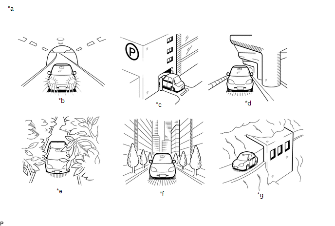
(a) Check if the vehicle is in a location where GPS signal reception is poor. If the vehicle is in such a place, relocate the vehicle and check if the GPS mark reappears.
HINT:
The GPS uses 24 satellites in 6 orbits. At any point in time, 4 satellites should be able to pinpoint your vehicle. However, GPS signals may not reach the vehicle due to influence from the surroundings, vehicle direction and time. For examples, see the following illustration.
OK:
The GPS mark is displayed.
Text in Illustration|
*a |
Example |
*b |
In a tunnel |
|
*c |
In a building |
*d |
Under an overpass |
|
*e |
On a forest or tree-lined path |
*f |
Between tall buildings |
|
*g |
Under a cliff or overhang |
- |
- |
| OK | |
SYSTEM RETURNS TO NORMAL |
|
|
3. |
CHECK GPS INFORMATION (OPERATION CHECK) |
.png)
(a) Enter the "System Sensor Check" screen. Refer to Check GPS & Vehicle Sensors
in Operation Check (See page .gif) ).
).
(b) Check how many of the following codes appear in the "Reception number" column.
HINT:
T or P appears.
OK:
At least 3 codes appear.
| OK | |
REPLACE NAVIGATION RECEIVER ASSEMBLY |
| NG | |
PROCEED TO NEXT SUSPECTED AREA SHOWN IN PROBLEM SYMPTOMS TABLE |
 Cursor or Map Rotates when Vehicle Stopped
PROCEDURE
1.
CHECK CONDITION
(a) Check with the customer if the vehicle has been turned by a turntable.
OK:
Vehicle has not been turned by a turntab ...
 Voice Guidance does not Function
PROCEDURE
1.
CHECK VOICE GUIDANCE SETTING
(a) Check that the voice guidance settings are not off.
OK:
Voice guidance settings are not off.
NG
C ...
Other materials:
Steering Pad Switch Circuit
DESCRIPTION
The forward recognition camera receives a lane departure alert switch signal
from the steering pad switch assembly.
WIRING DIAGRAM
for 2TR-FE
for 2GR-FKS
CAUTION / NOTICE / HINT
NOTICE:
The vehicle is equipped with a Supplemental Restraint System (SRS) which includes
compo ...
Skid Control Buzzer Circuit (C1A4A)
DESCRIPTION
Based on dynamic radar cruise control system operation, the forward recognition
camera provides warnings to the driver by sounding the skid control buzzer.
DTC C1A4A is stored when a malfunction is detected in the skid control buzzer
circuit.
DTC No.
Detectio ...
Parts Location
PARTS LOCATION
ILLUSTRATION
ILLUSTRATION
ILLUSTRATION
ILLUSTRATION
ILLUSTRATION
ILLUSTRATION
ILLUSTRATION
ILLUSTRATION
ILLUSTRATION
...
