Toyota Tacoma (2015-2018) Service Manual: Crankshaft Position Sensor
Components
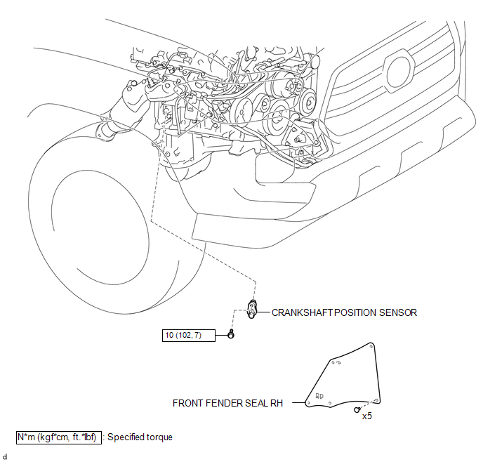
COMPONENTS
ILLUSTRATION
Installation
INSTALLATION
PROCEDURE
1. INSTALL CRANKSHAFT POSITION SENSOR
(a) Apply a light coat of engine oil to the O-ring of the crankshaft position sensor.
NOTICE:
- When reusing the crankshaft position sensor, inspect the O-ring.
- If the O-ring has scratches or cuts, replace the crankshaft position sensor.
(b) Install the crankshaft position sensor to the cylinder block sub-assembly with the bolt.
Torque:
10 N·m {102 kgf·cm, 7 ft·lbf}
(c) Connect the connector to the crankshaft position sensor.
2. INSTALL FRONT FENDER SEAL RH
HINT:
Use the same procedure as for the LH side (See page
.gif) ).
).
Removal
REMOVAL
PROCEDURE
1. REMOVE FRONT FENDER SEAL RH
HINT:
Use the same procedure as for the LH side (See page
.gif) ).
).
2. REMOVE CRANKSHAFT POSITION SENSOR
|
(a) Disconnect the connector from the crankshaft position sensor. |
|
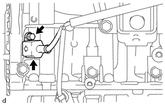
(b) Remove the bolt and crankshaft position sensor from the cylinder block sub-assembly.
 Installation
INSTALLATION
PROCEDURE
1. SET NO. 1 CYLINDER TO TDC/COMPRESSION
2. INSTALL CAMSHAFT TIMING GEAR BOLT
NOTICE:
There are different types of camshaft timing gearbolts. Make sure to check the
id ...
 Ecm
Ecm
Components
COMPONENTS
ILLUSTRATION
ILLUSTRATION
Installation
INSTALLATION
PROCEDURE
1. INSTALL NO. 2 ECM BRACKET
(a) Install the No. 2 ECM bracket to the ECM with the 2 screws.
Torque ...
Other materials:
Multi-terrain Select Indicator Light Remains ON
DESCRIPTION
Refer to Multi-terrain Select Indicator Light does not Come ON (See page
).
WIRING DIAGRAM
CAUTION / NOTICE / HINT
NOTICE:
When replacing the skid control ECU (master cylinder solenoid), perform
calibration (See page
).
Inspect the fuses for circuits related ...
Driver Side Seat Heater does not Operate
DESCRIPTION
When the seat heater switch on the air conditioning control assembly is operated,
the air conditioning amplifier assembly receives the signal. The air conditioning
amplifier assembly receives the signal and operates the front seat heater.
WIRING DIAGRAM
CAUTION / NOTICE / HINT
...
Compressor Lock Sensor Circuit (B1422/22)
SYSTEM DESCRIPTION
The ECM sends the engine speed signal to the air conditioning amplifier assembly
via CAN communication.
The air conditioning amplifier assembly reads the difference between compressor
speed and engine speed. When the difference becomes too large, the air conditioning
ampli ...
