Toyota Tacoma (2015-2018) Service Manual: Installation
INSTALLATION
CAUTION / NOTICE / HINT
HINT:
Perform "Inspection After Repairs" after replacing the fuel pump assembly (See
page .gif) ).
).
PROCEDURE
1. SET FUEL PUMP ASSEMBLY
HINT:
Perform "Inspection After Repairs" after replacing the fuel pump assembly (See
page ).
|
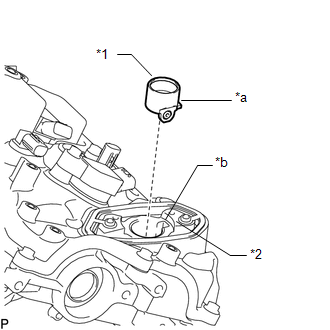
(a) Turn the crankshaft so that the flat surface of the camshaft is facing upward from the fuel pump assembly hole of the cylinder head cover sub-assembly. Text in Illustration
HINT: By performing the above procedure, the protruding part of the camshaft does not push up the drive face of the fuel pump when installing the fuel pump, thus making installation of the fuel pump and No. 1 fuel pipe sub-assembly easier. |
|
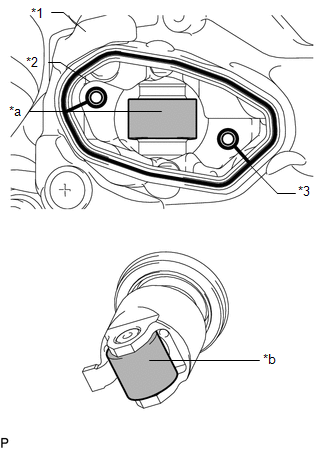
(b) Fill the cylinder head oil collection areas with 30 cc (1.8 cu.in.) of engine oil from the fuel pump hole of the cylinder head cover sub-assembly.
|
(c) Apply engine oil to the fuel pump drive cam and fuel pump lifter. Text in Illustration
|
|
(d) Install a new fuel pump spacer gasket to the cylinder head cover sub-assembly.
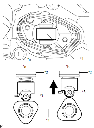
(e) Apply engine oil to the inside of the fuel pump lifter housing and the outside of the fuel pump lifter assembly.
|
(f) Set the fuel pump lifter housing on the fuel pump lifter assembly as shown in the illustration. Text in Illustration
NOTICE: Align the stopper key of the fuel pump lifter assembly with the key groove of the fuel pump lifter housing. |
|
(g) Apply engine oil to a new O-ring and install it to the fuel pump assembly.
NOTICE:
Do not damage the O-ring.
|
(h) Set the cylinder head cover sub-assembly on the fuel pump lifter guide and fuel pump assembly as shown in the illustration. |
|
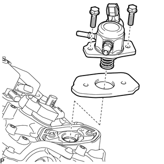
(i) Temporarily install the fuel pump assembly with the 2 bolts, leaving some allowance for left and right movement.
2. TEMPORARILY INSTALL NO. 1 FUEL PIPE SUB-ASSEMBLY
(a) Temporarily install the union nuts on the fuel delivery pipe side of the No. 1 fuel pipe sub-assembly until they are completely tightened.
(b) Temporarily install the union nuts on the fuel pump assembly side of the No. 1 fuel pipe sub-assembly until they are completely tightened.
NOTICE:
Do not damage the seals of the union nuts of the No. 1 fuel pipe sub-assembly when installing.
3. INSTALL FUEL PUMP ASSEMBLY
HINT:
Perform "Inspection After Repairs" after replacing the fuel pump (See page
).
(a) Uniformly tighten the 2 bolts in several steps to secure the fuel pump assembly to the cylinder head cover sub-assembly.
Torque:
26 N·m {265 kgf·cm, 19 ft·lbf}
4. INSTALL NO. 1 FUEL PIPE SUB-ASSEMBLY
|
(a) Using a 17 mm union nut wrench, tighten the union nuts on the fuel delivery pipe side of the No. 1 fuel pipe sub-assembly. Text in Illustration
Torque: Specified tightening torque : 35 N·m {357 kgf·cm, 26 ft·lbf} NOTICE:
HINT:
|
|
.png)
(b) Using a 17 mm union nut wrench, tighten the union nuts on the fuel pump assembly side of the No. 1 fuel pipe sub-assembly.
Torque:
Specified tightening torque :
35 N·m {357 kgf·cm, 26 ft·lbf}
NOTICE:
- Do not adjust the torque in the loosening direction.
- The No. 1 fuel pipe sub-assembly can be reused 10 times.
HINT:
- Calculate the torque wrench reading when changing the fulcrum length
of the torque wrench (See page ).
- When using a union nut wrench (fulcrum length of 30 mm (1.18 in.)) + torque wrench (fulcrum length of 180 mm (7.09 in.)): 30 N*m (306 kgf*cm, 22 ft.*lbf)
- This torque value is effective when the union nut wrench is parallel to the torque wrench.
- Install the union nut wrench parallel with the torque wrench.
5. INSTALL FUEL TUBE SUB-ASSEMBLY
(a) Install the fuel tube sub-assembly with the bolt.
Torque:
10 N·m {102 kgf·cm, 7 ft·lbf}
(b) Connect the fuel tube sub-assembly to the fuel pump assembly (See page
).
6. INSTALL WIRE HARNESS CLAMP BRACKET
(a) Install the wire harness clamp bracket with the 2 bolts.
Torque:
8.0 N·m {82 kgf·cm, 71 in·lbf}
7. INSTALL INTAKE MANIFOLD
(See page )
 Inspection
INSPECTION
PROCEDURE
1. INSPECT FUEL PUMP ASSEMBLY
(a) Measure the resistance according to the value(s) in the table below.
Standard Resistance:
Tester Connection
Condition ...
 Fuel Sender Gauge Assembly
Components
COMPONENTS
ILLUSTRATION
Inspection
INSPECTION
PROCEDURE
1. INSPECT FUEL SENDER GAUGE ASSEMBLY
(a) Check that the float moves smoothly between F and E.
Text in Ill ...
Other materials:
How To Proceed With Troubleshooting
CAUTION / NOTICE / HINT
Techstream can be used in steps 3, 6, 9 and 12.
PROCEDURE
1.
VEHICLE BROUGHT TO WORKSHOP
NEXT
2.
CUSTOMER PROBLEM ANALYSIS
...
Problem Symptoms Table
PROBLEM SYMPTOMS TABLE
HINT:
Troubleshooting of the theft deterrent system is based on the premise
that the power door lock control system, wireless door lock control system*1
and smart key system*2 are operating normally. Accordingly, before troubleshooting
the theft deterrent ...
Blind Spot Monitor Slave Module Beam Axis Inspection Incomplete (C1ABC)
DESCRIPTION
This DTC is stored when a beam axis inspection has not been performed for the
blind spot monitor sensor RH.
HINT:
This DTC is always stored after replacing a blind spot monitor sensor. The purpose
of this DTC is to ensure that beam axis inspection is performed. Completing the
be ...
