Toyota Tacoma (2015-2018) Service Manual: Driver Side Power Window does not Operate with Power Window Master Switch
DESCRIPTION
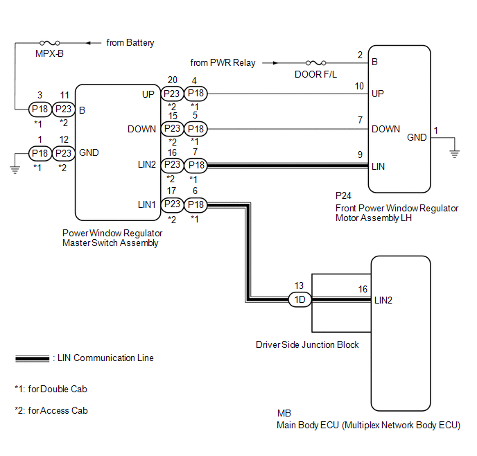
When the engine is running or the ignition switch is ON, the front power window regulator motor assembly LH is operated by the power window regulator master switch assembly. The front power window regulator motor assembly LH has motor, regulator, and ECU functions.
HINT:
If the pulse sensor built into the front power window regulator motor assembly LH malfunctions, the power window control system enters fail-safe mode. The remote up/down and auto up/down functions cannot be operated during fail-safe mode. However, the power window can be closed by holding the power window regulator master switch assembly at the auto up position, and opened manually by pushing down the power window regulator master switch assembly.
WIRING DIAGRAM
CAUTION / NOTICE / HINT
NOTICE:
- The power window control system uses the LIN communication system. Inspect
the communication function by following How to Proceed with Troubleshooting.
Troubleshoot the power window control system after confirming that the communication
system is functioning properly (See page
.gif) ).
). - If the front power window regulator motor assembly LH has been replaced
with a new one, initialize the power window control system (See page
).
- Inspect the fuses for circuits related to this system before performing the following procedure.
- When the ECU determines that the front power window regulator motor assembly LH has a malfunction, DTC B2311 is set.
PROCEDURE
|
1. |
READ VALUE USING TECHSTREAM (MAIN BODY) |
(a) Connect the Techstream to the DLC3.
(b) Turn the ignition switch to ON.
(c) Turn the Techstream on.
(d) Enter the following menus: Body Electrical / Main Body / Data List.
(e) Read the Data List according to the display on the Techstream.
Main Body (Main Body ECU)|
Tester Display |
Measurement Item/Range |
Normal Condition |
Diagnostic Note |
|---|---|---|---|
|
Communication D-Door Motor |
Connection status between front power window regulator motor assembly LH and main body ECU / OK or STOP |
OK: Normal communication STOP: Communication stopped |
- |
|
Communication Master SW |
Connection status between multiplex network master switch and main body ECU / OK or STOP |
OK: Normal communication STOP: Communication stopped |
- |
OK:
On the Techstream screen, OK is displayed.
| NG | .gif) |
GO TO LIN COMMUNICATION SYSTEM (Proceed to How to Proceed with Troubleshooting) |
|
.gif)
|
2. |
READ VALUE USING TECHSTREAM (D-DOOR MOTOR) |
(a) Enter the following menus: Body Electrical / D-Door Motor / Data List.
(b) Read the Data List according to the display on the Techstream.
D-Door Motor (Front Power Window Regulator Motor Assembly LH)|
Tester Display |
Measurement Item/Range |
Normal Condition |
Diagnostic Note |
|---|---|---|---|
|
D Door P/W Up SW |
Driver side power window manual up switch signal / ON or OFF |
ON: Driver side power window manual up switch operated OFF: Driver side power window manual up switch not operated |
- |
|
D Door P/W Down SW |
Driver side power window manual down switch signal / ON or OFF |
ON: Driver side power window manual down switch operated OFF: Driver side power window manual down switch not operated |
- |
OK:
On the Techstream screen, ON or OFF is displayed accordingly.
| NG | |
GO TO STEP 4 |
|
|
3. |
PERFORM ACTIVE TEST USING TECHSTREAM (D-DOOR MOTOR) |
(a) Enter the following menus: Body Electrical / D-Door Motor / Active Test.
(b) Perform the Active Test according to the display on the Techstream.
CAUTION:
Be careful to avoid injuries as this test causes vehicle parts to move. During the Active Test, the jam protection function will not operate.
D-Door Motor (Front Power Window Regulator Motor Assembly LH)|
Tester Display |
Test Part |
Control Range |
Diagnostic Note |
|---|---|---|---|
|
Power Window |
Power window |
OFF / UP / DOWN |
- |
HINT:
Up and down movement does not occur if the arrow is not pressed and held.
OK:
Driver side power window operates normally.
| OK | |
REPLACE MAIN BODY ECU |
| NG | |
REPLACE FRONT POWER WINDOW REGULATOR MOTOR ASSEMBLY LH |
|
4. |
CHECK HARNESS AND CONNECTOR (MULTIPLEX NETWORK MASTER SWITCH ASSEMBLY - FRONT POWER WINDOW REGULATOR MOTOR ASSEMBLY LH) |
(a) for Double Cab:
(1) Disconnect the P18 power window regulator master switch assembly connector.
(2) Disconnect the P24 front power window regulator motor assembly LH connector.
(3) Measure the resistance according to the value(s) in the table below.
Standard Resistance:
|
Tester Connection |
Condition |
Specified Condition |
|---|---|---|
|
P18-4 (UP) - P24-10 (UP) |
Always |
Below 1 Ω |
|
P18-5 (DOWN) - P24-7 (DOWN) |
Always |
Below 1 Ω |
|
P18-4 (UP) - Body ground |
Always |
10 kΩ or higher |
|
P18-5 (DOWN) - Body ground |
Always |
10 kΩ or higher |
|
P24-10 (UP) - Body ground |
Always |
10 kΩ or higher |
|
P24-7 (DOWN) - Body ground |
Always |
10 kΩ or higher |
(b) for Access Cab:
(1) Disconnect the P23 power window regulator master switch assembly connector.
(2) Disconnect the P24 front power window regulator motor assembly LH connector.
(3) Measure the resistance according to the value(s) in the table below.
Standard Resistance:
|
Tester Connection |
Condition |
Specified Condition |
|---|---|---|
|
P23-20 (UP) - P24-10 (UP) |
Always |
Below 1 Ω |
|
P23-15 (DOWN) - P24-7 (DOWN) |
Always |
Below 1 Ω |
|
P23-20 (UP) - Body ground |
Always |
10 kΩ or higher |
|
P23-15 (DOWN) - Body ground |
Always |
10 kΩ or higher |
|
P24-10 (UP) - Body ground |
Always |
10 kΩ or higher |
|
P24-7 (DOWN) - Body ground |
Always |
10 kΩ or higher |
| NG | |
REPAIR OR REPLACE HARNESS OR CONNECTOR |
|
|
5. |
REPLACE POWER WINDOW REGULATOR MASTER SWITCH ASSEMBLY |
(a) Replace the power window regulator master switch assembly (See page
).
|
|
6. |
CHECK MANUAL UP / DOWN FUNCTION (FOR DRIVER SIDE) |
(a) Check that the driver side door power window moves when the manual up/down
function of the power window regulator master switch assembly is operated (See page
).
OK:
Driver side manual up/down function is normal.
| OK | |
END (POWER WINDOW REGULATOR MASTER SWITCH ASSEMBLY WAS DEFECTIVE) |
| NG | |
REPLACE FRONT POWER WINDOW REGULATOR MOTOR ASSEMBLY LH |
 Glass Position Initialization Incomplete (B2313)
DESCRIPTION
The power window regulator motor assembly is operated by the power window regulator
master switch assembly or power window regulator switch assembly. The power window
regulator motor ...
 Front Passenger Side Power Window does not Operate with Front Passenger Side
Power Window Switch
Front Passenger Side Power Window does not Operate with Front Passenger Side
Power Window Switch
DESCRIPTION
When the engine is running or the ignition switch is ON, the front power window
regulator motor assembly RH is operated by the front power window regulator switch
assembly RH. The fro ...
Other materials:
Microphone Amplifier
Components
COMPONENTS
ILLUSTRATION
*A
w/o Sliding Roof
*B
w/ Sliding Roof
*1
TELEPHONE MICROPHONE ASSEMBLY
-
-
Removal
REMOVAL
PROCEDURE
1. REMOVE ROOF HEADLINING ASSEMBLY (for Double ...
Ambient Temperature Sensor
Components
COMPONENTS
ILLUSTRATION
Inspection
INSPECTION
PROCEDURE
1. INSPECT AMBIENT TEMPERATURE SENSOR
(a) Measure the resistance according to the value(s) in the table below.
Standard resistance:
Tester Connection
Condition
...
Lost Communication with ECM / PCM "A" (U0100,U0125,U0126,U0129)
DESCRIPTION
These DTCs are stored when a communication malfunction occurs between ECUs that
perform pre-collision system control.
DTC No.
Detection Item
DTC Detection Condition
Trouble Area
U0100
Lost Communication with ECM ...
