Toyota Tacoma (2015-2018) Service Manual: Engine Coolant Temperature Sensor
Components
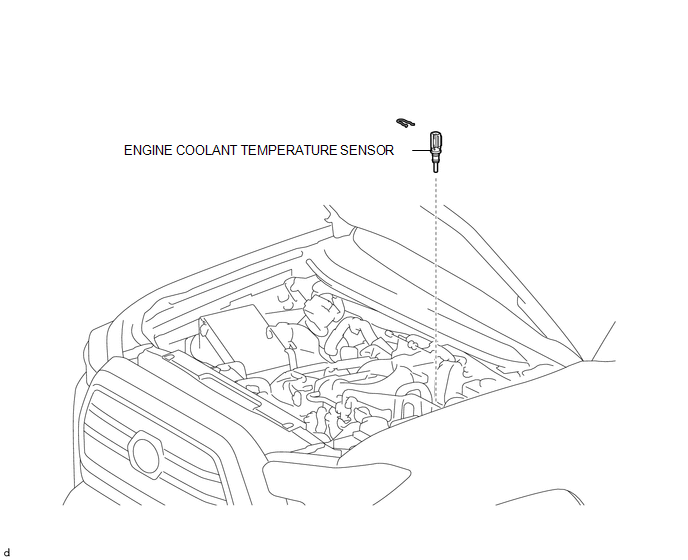
COMPONENTS
ILLUSTRATION
Inspection
INSPECTION
PROCEDURE
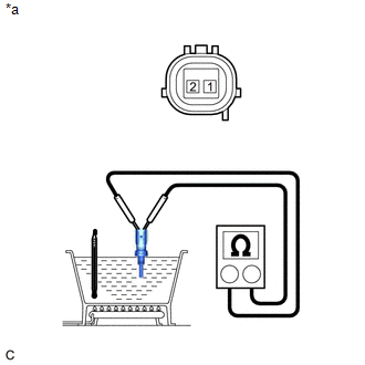
1. INSPECT ENGINE COOLANT TEMPERATURE SENSOR
(a) Partially immerse the engine coolant temperature sensor in water and warm up the water.
|
(b) Measure the resistance according to the value(s) in the table below. Text in Illustration
Standard Resistance:
NOTICE: When checking the engine coolant temperature sensor in water, keep the terminals dry. After the check, wipe the sensor dry. If the result is not as specified, replace the engine coolant temperature sensor. |
|
Installation
INSTALLATION
PROCEDURE
1. INSTALL ENGINE COOLANT TEMPERATURE SENSOR
HINT:
Perform "Inspection After Repair" after replacing the engine coolant temperature
sensor (See page .gif) ).
).
(a) Apply a light coat of engine coolant to the O-ring of the engine coolant temperature sensor.
NOTICE:
- When reusing the engine coolant temperature sensor, inspect the O-ring.
- Make sure that the O-ring is not cracked or jammed when installing it on the rear water by-pass joint.
- Replace with a new part if it is dropped or if it receives a strong impact.
(b) Install the engine coolant temperature sensor to the rear water by-pass joint with the clip.
(c) Connect the connector to the engine coolant temperature sensor.
2. INSTALL INTAKE MANIFOLD
(See page )
Removal
REMOVAL
PROCEDURE
1. REMOVE INTAKE MANIFOLD
(See page .gif) )
)
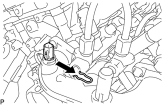
2. REMOVE ENGINE COOLANT TEMPERATURE SENSOR
(a) Disconnect the connector from the engine coolant temperature sensor.
|
(b) Remove the clip and engine coolant temperature sensor from the rear water by-pass joint. |
|
 Ecm
Ecm
Components
COMPONENTS
ILLUSTRATION
ILLUSTRATION
Installation
INSTALLATION
PROCEDURE
1. INSTALL NO. 2 ECM BRACKET
(a) Install the No. 2 ECM bracket to the ECM with the 2 screws.
Torque ...

Other materials:
Reassembly
REASSEMBLY
PROCEDURE
1. INSTALL REAR BUMPER SIDE STAY LH
(a) Install the rear bumper side stay LH with the 2 bolts.
Torque:
30 N·m {306 kgf·cm, 22 ft·lbf}
2. INSTALL REAR BUMPER SIDE STAY RH
HINT:
Use the same procedure as for ...
Reassembly
REASSEMBLY
PROCEDURE
1. INSTALL OIL PUMP COVER
(a) Apply fresh engine oil to the drive and driven rotors.
(b) Place the drive and driven rotors into the timing chain cover assembly
with the marks facing the oil pump cover side.
Text in Illustration
*a
...
System Description
SYSTEM DESCRIPTION
1. ENGINE IMMOBILISER SYSTEM DESCRIPTION
The engine immobiliser system is designed to prevent the vehicle from being stolen.
This system uses the transponder key ECU assembly that stores the key ID codes of
authorized ignition keys. If an attempt is made to start the engine ...
