Toyota Tacoma (2015-2018) Service Manual: Rear Console Box
Components
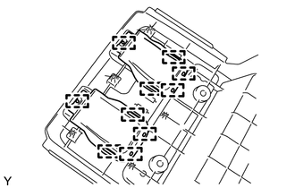
COMPONENTS
ILLUSTRATION
ILLUSTRATION
Installation
INSTALLATION
PROCEDURE
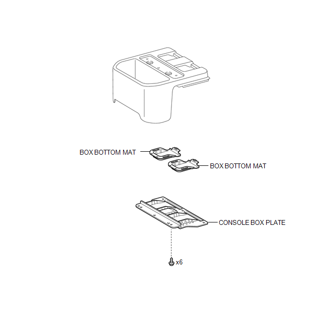
1. INSTALL BOX BOTTOM MAT
(a) Engage the 10 guides and install the 2 box bottom mats.
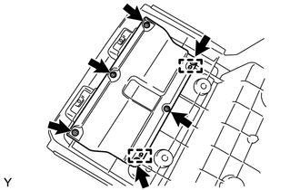
2. INSTALL CONSOLE BOX PLATE
(a) Engage the 2 guides and install the console box plate.
(b) Install the 6 screws.
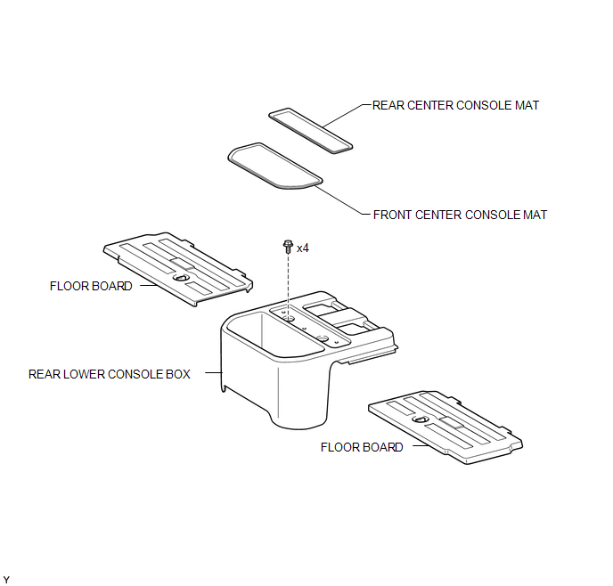
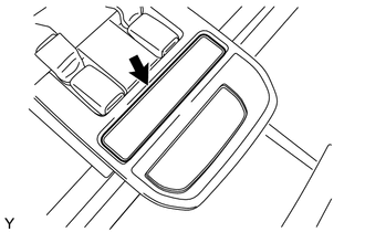
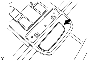
3. INSTALL REAR LOWER CONSOLE BOX
(a) Engage the 2 guides and install the lower console box.
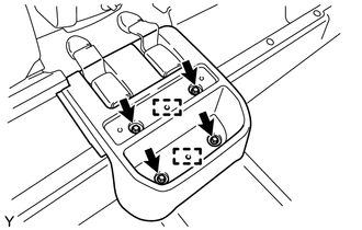
(b) Install the 4 bolts.
4. INSTALL FRONT CENTER CONSOLE MAT
(a) Install the front center console mat.
5. INSTALL REAR CENTER CONSOLE MAT
(a) Install the rear center console mat.
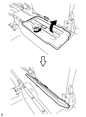
6. INSTALL FLOOR BOARD
|
(a) Return the floor board and engage the lock. HINT: Use the same procedure for both sides. |
|
Removal
REMOVAL
PROCEDURE
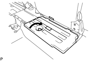
1. REMOVE FLOOR BOARD
|
(a) Release the lock and fasten the floor board to the seat bottom. HINT: Use the same procedure for both sides. |
|
2. REMOVE REAR CENTER CONSOLE MAT
|
(a) Remove the front center console mat. |
|
3. REMOVE FRONT CENTER CONSOLE MAT
|
(a) Remove the rear center console mat. |
|
4. REMOVE REAR LOWER CONSOLE BOX
|
(a) Remove the 4 bolts. |
|
(b) Disengage the 2 guides and remove the lower console box.
5. REMOVE CONSOLE BOX PLATE
|
(a) Remove the 6 screws. |
|
(b) Disengage the 2 guides and remove the console box plate.
6. REMOVE BOX BOTTOM MAT
|
(a) Disengage the 10 guides and remove the 2 box bottom mats. |
|
 Front Floor Footrest
Components
COMPONENTS
ILLUSTRATION
Installation
INSTALLATION
PROCEDURE
1. INSTALL FRONT FLOOR FOOTREST
(a) Engage the 2 clips to install the front floor footrest.
...

Other materials:
Cleaning and protecting the vehicle interior
The following procedures will help protect your vehicle’s interior and keep
it in top condition:
■ Protecting the vehicle interior
Remove dirt and dust using a vacuum cleaner. Wipe dirty surfaces with a cloth
dampened with lukewarm water.
■ Cleaning the leather areas
● Re ...
Problem Symptoms Table
PROBLEM SYMPTOMS TABLE
HINT:
Proceed to the troubleshooting for each circuit in the table below.
Symptom
Suspected Area
See page
Passenger seat occupant conditions and displayed passenger airbag ON/OFF
indicator do not correspond
Tr ...
Front Radar Sensor Region Code Mismatch (C1A0A)
DESCRIPTION
When the destination information in the millimeter wave radar sensor assembly
and forward recognition camera do not match, DTC C1A0A is stored.
DTC No.
Detection Item
DTC Detection Condition
Trouble Area
MIL
C1A0 ...
