Toyota Tacoma (2015-2018) Service Manual: Four Wheel Drive (4WD) Range Signal Circuit Range / Performance (P279E)
DESCRIPTION
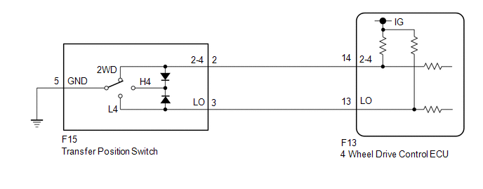
When the transfer position switch is switched, the 2-4 terminal and LO terminal change to one of the following ON/OFF combinations listed in the table below.
|
Terminal |
2WD |
Between 2WD and H4 |
H4 |
Between H4 and L4 |
L4 |
|---|---|---|---|---|---|
|
2-4 |
ON |
OFF |
ON |
OFF |
OFF |
|
LO |
OFF |
OFF |
ON |
OFF |
ON |
This DTC is detected if the transfer position switch 2-4 terminal and LO terminal signals are simultaneously received.
|
DTC No. |
Detection Item |
DTC Detection Condition |
Trouble Area |
|---|---|---|---|
|
P279E |
Four Wheel Drive (4WD) Range Signal Circuit Range / Performance |
|
|
WIRING DIAGRAM
PROCEDURE
|
1. |
CHECK HARNESS AND CONNECTOR (4 WHEEL DRIVE CONTROL ECU - TRANSFER POSITION SWITCH) |
(a) Disconnect the F13 4 wheel drive control ECU connector.
(b) Disconnect the F15 transfer position switch connector.
(c) Measure the resistance according to the value(s) in the table below.
Standard Resistance:
|
Tester Connection |
Condition |
Specified Condition |
|---|---|---|
|
F13-14 (2-4) - F15-2 (2-4) |
Always |
Below 1 Ω |
|
F13-13 (LO) - F15-3 (LO) |
Always |
Below 1 Ω |
|
F15-5 (GND) - Body ground |
Always |
Below 1 Ω |
|
F13-14 (2-4) or F15-2 (2-4) - Body ground |
Always |
10 kΩ or higher |
|
F13-13 (LO) or F15-3 (LO) - Body ground |
Always |
10 kΩ or higher |
|
F13-14 (2-4) or F15-2 (2-4) - F13-13 (LO) or F15-3 (LO) |
Always |
10 kΩ or higher |
| NG | .gif) |
REPAIR OR REPLACE HARNESS OR CONNECTOR |
|
.gif)
|
2. |
CHECK TRANSFER POSITION SWITCH |
|
(a) Remove the transfer position switch with its connector still connected. |
|
(b) Measure the voltage according to the value(s) in the table below.
Standard Voltage:
|
Tester Connection |
Switch Condition |
Specified Condition |
|---|---|---|
|
F15-2 (2-4) - Body ground |
Ignition switch ON 2WD position |
Below 1.5 V |
|
Ignition switch ON H4 position |
Below 1.5 V |
|
|
Ignition switch ON L4 position |
10 to 14 V |
|
|
F15-3 (LO) - Body ground |
Ignition switch ON 2WD position |
10 to 14 V |
|
Ignition switch ON H4 position |
Below 1.5 V |
|
|
Ignition switch ON L4 position |
Below 1.5 V |
|
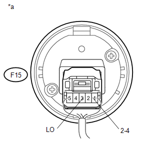
*a |
Component with harness connected (Transfer Position Switch) |
| OK | |
REPLACE 4 WHEEL DRIVE CONTROL ECU |
| NG | |
REPLACE TRANSFER POSITION SWITCH |
 Transfer Shift Motor Control Circuit Circuit Open (P17A8)
DESCRIPTION
This DTC is output when an open circuit in the transfer shift motor drive circuit
is detected.
DTC No.
Detection Item
DTC Detection Condition
...
 Transfer Shift Motor Control Circuit Low (P17A9)
DESCRIPTION
This DTC is output when a short to ground in the transfer shift motor and A.D.D.
shift motor drive circuit is detected.
DTC No.
Detection Item
DTC Dete ...
Other materials:
Problem Symptoms Table
PROBLEM SYMPTOMS TABLE
HINT:
Use the table below to help determine the causes of the problem symptom.
The potential causes of the symptoms are listed in order of probability
in the "Suspected Area" column of the table. Check each symptom by checking
the suspected area ...
System Description
SYSTEM DESCRIPTION
1. GENERAL
(a) The air conditioning system has the following controls.
Control
Outline
Manual Control
The air conditioner amplifier assembly controls the damper positions
(air inlet control damper, air mix control damper and ...
On-vehicle Inspection
ON-VEHICLE INSPECTION
PROCEDURE
1. INSPECT AIR CONDITIONER PRESSURE SENSOR (for Automatic Air Conditioning System)
(a) Check the wire harness.
(1) Disconnect the A34 air conditioner pressure sensor connector.
(2) Disconnect the A35 and A36 air conditioning amplifier assembly connector.
...
