Toyota Tacoma (2015-2018) Service Manual: Transfer Shift Motor Control Circuit Circuit Open (P17A8)
DESCRIPTION
This DTC is output when an open circuit in the transfer shift motor drive circuit is detected.
|
DTC No. |
Detection Item |
DTC Detection Condition |
Trouble Area |
|---|---|---|---|
|
P17A8 |
Transfer Shift Motor Control Circuit Circuit Open |
|
|
WIRING DIAGRAM
Refer to DTC P17A9 (See page .gif) ).
).
PROCEDURE
|
1. |
CHECK HARNESS AND CONNECTOR (4 WHEEL DRIVE CONTROL ECU - TRANSFER SHIFT ACTUATOR ASSEMBLY) |
(a) Disconnect the F12 4 wheel drive control ECU connector.
(b) Disconnect the T4 transfer shift actuator assembly connector.
(c) Measure the resistance according to the value(s) in the table below.
Standard Resistance:
|
Tester Connection |
Condition |
Specified Condition |
|---|---|---|
|
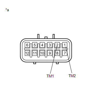
F12-8 (TM1) - T4-2 (TM1) |
Always |
Below 1 Ω |
|
F12-7 (TM2) - T4-1 (TM2) |
Always |
Below 1 Ω |
| NG | .gif) |
REPAIR OR REPLACE HARNESS OR CONNECTOR |
|
.gif)
|
2. |
INSPECT TRANSFER SHIFT ACTUATOR ASSEMBLY (TRANSFER SHIFT MOTOR) |
|
(a) Disconnect the T4 transfer shift actuator assembly connector. |
|
(b) Measure the resistance according to the value(s) in the table below.
Standard Resistance:
|
Tester Connection |
Condition |
Specified Condition |
|---|---|---|
|
2 (TM1) - 1 (TM2) |
Always |
1.5 to 10 Ω |
|
*a |
Component without harness connected (Transfer Shift Actuator Assembly) |
| OK | |
REPLACE 4 WHEEL DRIVE CONTROL ECU |
| NG | |
REPLACE TRANSFER SHIFT ACTUATOR ASSEMBLY |
 Automatic Disconnecting Differential Motor Limit Switch Circuit (P17A4)
DESCRIPTION
When the A.D.D. actuator switches between 2WD and 4WD, the DL1 and DL2 terminals
of the limit switch and ADD terminal of the A.D.D. position switch change to one
of the following ON/O ...
 Four Wheel Drive (4WD) Range Signal Circuit Range / Performance (P279E)
DESCRIPTION
When the transfer position switch is switched, the 2-4 terminal and LO terminal
change to one of the following ON/OFF combinations listed in the table below.
Terminal
...
Other materials:
Camshaft
Components
COMPONENTS
ILLUSTRATION
ILLUSTRATION
ILLUSTRATION
ILLUSTRATION
ILLUSTRATION
*1
FUEL PUMP ASSEMBLY
*2
FUEL PUMP LIFTER ASSEMBLY
*3
FUEL PUMP LIFTER GUIDE
*4
FUEL PUMP SPACER GAS ...
Data List / Active Test
DATA LIST / ACTIVE TEST
NOTICE:
In the table below, the values listed under "Normal Condition" are reference
values. Do not depend solely on these reference values when deciding whether a part
is faulty or not.
HINT:
Using the Techstream to read the Data List allows the values or s ...
Removal
REMOVAL
CAUTION / NOTICE / HINT
Text in Illustration
*a
Object Exceeding Weight Limit of Transmission Jack
Be sure to perform this procedure with several people as the rear differential
carrier assembly is very heavy.
Be sure to follow the procedure ...
